The circuit breaker can be applied at both sides of a branch and at an element.
The circuit breaker can be used in combination with a protection relay. More than one circuit breakers can be combined with a single differential protection relay.
The circuit breaker cannot be used in combination with another switching or protecting device in the same field.
The circuit breaker can be added by selecting a branch or an element together with the corresponding node and choose Insert | Switches and protections | Circuit breaker.
A circuit breaker that has been copied can be pasted in several places at the same time. To do this, select the relevant feeders (a feeder is defined as a branch or element with the connecting node) and choose Start | Clipboard | Paste special | Paste load switch in all selected feeders.
PARAMETERS
General
Parameter |
Default |
Unit |
Description |
Name |
|
|
Circuit breaker name |
Protection |
|
|
|
Current 1 |
no |
|
First overcurrent protection present, active and directional sensitivity RCA |
Current 2 |
no |
|
Second overcurrent protection present, active and directional sensitivity RCA |
Earth fault 1 |
no |
|
First earth fault protection present, active and directional sensitivity RCA |
Earth fault 2 |
no |
|
Second earth fault protection present, active and directional sensitivity RCA |
Voltage |
no |
|
Voltage protection present, active and directional sensitivity RCA |
Differential |
no |
|
Differential protection present and active |
Distance |
no |
|
Distance protection present and active |
Unbalance |
no |
|
Unbalance protection present and active |
Thermal |
no |
|
Thermal protection present and active |
Earth fault diff. |
no |
|
Earth fault differential protection present and active |
Vector-jump |
no |
|
Vector-jump protection present and active |
Frequency |
no |
|
Frequency protection present and active |
Transfer tripping ability |
no |
|
Transfer tripping present, directional sensitivity and delay time |
Reserve ability |
no |
|
Reserve ability present |
Blocking ability |
no |
|
Blocking ability present |
Directional sensitivity
The directional sensitivity can be defined by the parameter RCA, rotating the "measured" voltage. As a consequence the protection trips if the current vector angle with reference to the voltage vector angle lies between RCA+90° and RCA-90°. In the case of a regular overcurrent protection, the angle is calculated between the phase voltage and phase current. In the case of an earth fault protection, the angle is calculated between zero sequence voltage and current.
Transfer trip
A transfer trip signal is optionally available when a circuit breaker is protected. Surrounding circuit breakers can be switched off (with a delay) if this circuit breaker trips.
As soon as 'Transfer trip ability' is checked, the 'Tools' tab becomes visible. The connections to protections in other circuit breakers can be entered on this tab. This works best when the connected circuit breakers are also selected.
Reserve
A reserve circuit breaker is optionally available. In the case of a reserve circuit breaker, a protection can open other specific circuit breakers at the moment a circuit breaker refuses to open. An additional time delay can be defined.
As soon as 'Reserve ability' is checked, the 'Tools' tab becomes visible. The connections to protections in other circuit breakers can be entered on this tab. This works best when the connected circuit breakers are also selected.
Blocking
A blocking circuit breaker is optionally available. A protection in this circuit breaker can block a protection in another circuit breaker at the moment the protection is triggered.
As soon as 'Blocking ability' is checked, the 'Tools' tab becomes visible. The connections to protections in other circuit breakers can be entered on this tab. This works best when the connected circuit breakers are also selected.
Circuit breaker
The circuit breaker has been equipped with a type specification, that has the following parameters:
Parameter |
Default |
Unit |
Description |
Type |
|
|
Circuit breaker type name. |
Short |
|
|
Circuit breaker short name. |
Unom |
0 |
kV |
Rated voltage |
Inom |
0 |
A |
Rated current |
Switch time |
0 |
s |
Duration for the switch to isolate |
Ik,make |
0 |
kA |
Maximum making current |
Ik,break |
0 |
kA |
Maximum breaking current |
Ik,dynamic |
0 |
kA |
Maximum dynamic current |
Ik,thermal |
0 |
kA |
Maximum thermal short circuit current |
at t,thermal |
0 |
s |
Maximum thermal short circuit duration |
Protection
One or more of the following protection relays can be added to the circuit breaker. See:
•Vector-jump;
•Frequency.
Reliability
The circuit breaker reliability parameters are listed below.
Parameter |
Default |
Unit |
Description |
No operation probability |
0 |
|
Possibility that the switch refuses to isolate in case of a short circuit |
Failure frequency |
0 |
per year |
Mean number of occurrences that the switch fails (short circuit) |
Repair duration |
0 |
minutes |
Mean duration of repair or replacement |
Remote indication |
no |
yes / no |
Presence of remote status indication |
Remote control |
no |
yes / no |
Presence of remote control |
Protection refusing (this session only) |
no |
|
Protection refuses; this is not saved in the network file |
Refusing (only during this session) |
no |
|
The switch refuses to turn off; this is not saved in the network file |
The remote indication influences the fault observation and fault location time (short/long) in the reliability calculations and the remote control influences the fault isolation and switching times (short/long).
Presentation
The circuit breaker is shown on the screen with a cross or with two points.
If the circuit breaker is equipped with a active protection relay, the cross is extended with one transverse line for each protection relay.
The graphical representation can be further defined on this tab. See also: Presentation Components
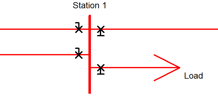
Extended protection indication
In the circuit diagram, each active protection relay on a circuit breaker is represented by a little transverse line on the circuit breaker symbol. For directional sensitive relays, this line points into the corresponding direction. The picture below shows two directional sensitive and two non-directional sensitive protection devices.