A current or overcurrent protection in Vision is part of a circuit breaker. For each circuit breaker two current protective devices can be defined. In this way different directional sensitivity settings (forward, backward and undirected) can be combined in a flexible way.
Directional sensitivity of an current protection can be defined as:
•backward (<), directed away from the branch or element as seen from the node
•undirected (<>)
•forward (>), directed towards the branch or element as seen from the node
The directional sensitivity can be set at the level of the circuit breaker under tab General.
For current protection time-current characteristic can be defined. The protective devices are divided in 6 different sorts:
•curve (current-time)
•fixed time
•inverse
•special
•specific
•LSI
Parameters
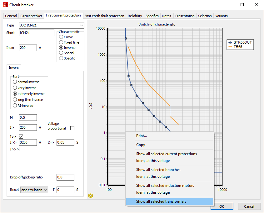
Besides the time-current curve of respective protection device it is also possible to visualize on the plot the curves/characteristics of other selected current protections, cables and lines, motors and transformers. Click with the right mouse button on the plot of the characteristic and for instance choose Show all selected current protections or Idem, at this voltage in the pop-up window that will appear. See also: Protections.
Parameter |
Default |
Unit |
Description |
Type |
|
|
Predefined type from component database |
Short |
|
|
Short description of type, maximum 10 symbols |
Inom |
0 |
A |
Nominal current of protective device (used only for info) |
t,input |
0 |
s |
Pickup time |
t,output |
0 |
s |
Operation output time |
Characteristic |
Curve |
|
Sort of characteristic (curve, definite time, inverse, special, specific) |
Curve |
|
|
|
I1 ... I16 |
0 |
A |
Current values of 16 points on the time-current curve |
t1 ... t16 |
0 |
s |
Time values of 16 points on the time-current curve |
Definite time |
|
|
|
I> |
0 |
A |
Current value of slow protection stage |
t> |
0 |
s |
Time value of slow protection stage |
I>> |
0 |
A |
Current value of medium protection stage (in case of 2 or 3 stages) |
t>> |
0 |
s |
Time value of medium protection stage (in case of 2 or 3 stages) |
I>>> |
0 |
A |
Current value of fast protection stage (in case of 3 stages) |
t>>> |
0 |
s |
Time value of fast protection stage (in case of 3 stages) |
Drop-off/pick-up ratio |
1 |
|
Ratio of the drop-off current value of the relay to the pickup value |
t,reset |
|
s |
Reset time (0 = instant) |
Inverse |
|
|
|
Sort |
normal |
|
Sort of inverse characteristic: normal / very / extremely / long time / RI-inverse |
M |
1 |
|
factor m (Time Multiplier Setting) |
I> |
0 |
A |
Current value of slow protection stage |
I>> |
0 |
A |
Current value of medium protection stage |
t>> |
0 |
s |
Time value of medium protection stage |
I>>> |
0 |
A |
Current value of fast protection stage |
t>>> |
0 |
s |
Time value of fast protection stage |
Id |
20 |
|
Factor of I> from where the protection starts to behave as definite time |
Voltage proportional |
0 |
|
Voltage dependency of inverse overcurrent characteristic |
Drop-off/pick-up ratio |
1 |
|
Ratio of the drop-off current value of the relay to the pickup value |
Reset |
Disc emulation |
|
Reset of inverse characteristic (disc emulation, fixed time) |
T |
0 |
s |
Reset time (0 = instant) |
Special |
|
|
|
alfa |
1 |
|
factor alfa |
beta |
1 |
|
factor beta |
c |
1 |
|
factor c |
d |
1 |
|
factor d |
e |
0 |
s |
factor e (extra time) |
m |
1 |
|
factor m (Time Multiplier Setting) |
I> |
0 |
A |
Current value of slow protection stage |
I>> |
0 |
A |
Current value of medium protection stage |
t>> |
0 |
s |
Time value of medium protection stage |
I>>> |
0 |
A |
Current value of fast protection stage |
t>>> |
0 |
s |
Time value of fast protection stage |
Id |
20 |
|
Factor of I> from where the protection starts to behave as definite time |
Drop-off/pick-up ratio |
1 |
|
Ratio of the drop-off current value of the relay to the pickup value |
t,reset |
0 |
s |
Reset time (0 = instant) |
Specific |
|
|
|
HV-fuse |
|
|
Specific characteristic of relay WIC1 (Woodward SEG) |
FR-fuse |
|
|
Specific characteristic of relay WIC1 (Woodward SEG) |
LSI |
|
|
|
I> |
0 |
A |
Current for slow tripping |
t |
0 |
s |
Time at @I in I²t, from slow tripping |
@I |
0 |
A |
Current at t in I²t, of slow tripping |
alfa |
2 |
|
Exponent of I in Ialfat |
I>> |
0 |
A |
Current for medium tripping |
t>> of t |
0 |
s |
Time of medium tripping or time at @I in I²t, of medium tripping |
@I |
0 |
A |
Current at t in I²t, of medium tripping |
I>>> |
0 |
A |
Current for quick tripping |
t>>> |
0 |
s |
Time of rapid tripping |
Drop-off/pick-up ratio |
1 |
|
Ratio of the drop-off current value of the relay to the pickup value |
The parameters starting from I> are applicable/not applicable depending on the characteristic.
Modelling
Directional sensitivity
The directional sensitivity is specified in the general parameters of the circuit breaker. The direction can be set there as forward, backward or undirected. In case the protection is directional, the RCA (Relay Characteristic Angle) can be specified. Different ways exist to determine the direction of the current, based on the measured currents and voltages. For a directional current protection the ‘90° Quadrature Connection’ is the standard connection method. The measurement of the voltage takes place in the undisturbed phases, in this manner a sufficiently large voltage is available (phase to phase voltage), as the voltage in the disturbed phase can drop to zero. For instances, for the protection of phase a the phase current Ia and phase to phase voltage Vbc are used. The phase to phase voltage is rotated with the RCA to ensure maximum sensitivity. In case of an earth fault protection the zero sequence voltage and current are considered (these are not rotated by 90°).
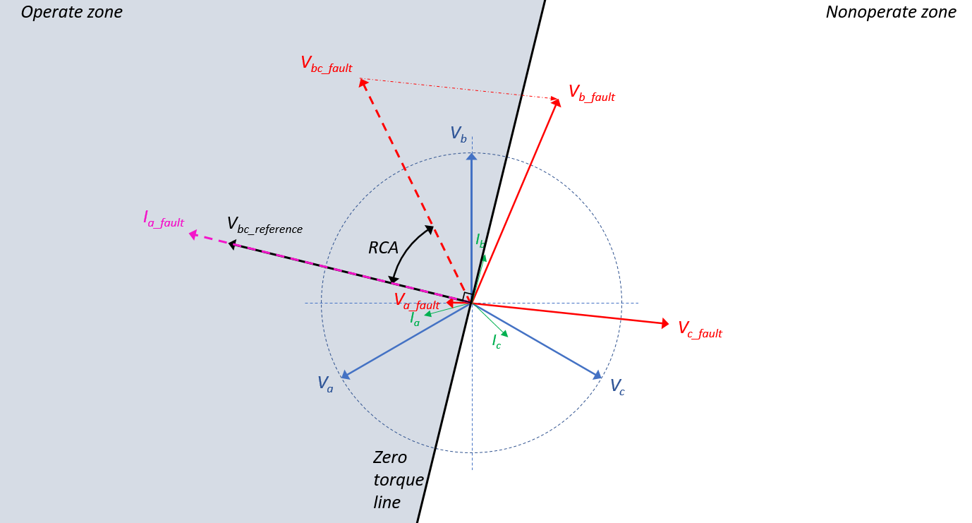
The maximum sensitivity of the directional power relays can be reached if the reference voltage is in phase with the fault current, in this example in phase with Ia_fault. The extra rotation angle, RCA, is in this case 50°. The directional element will allow the tripping of the relay if the current phase Ia_fault is located in the grey area of the above figure.
Curve
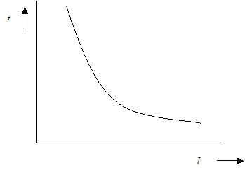
The curve is most often used to model the tripping behaviour of a fuse. The characteristic of a fuse is given in the diagram below. The points of the curve can be defined in the types file (up to a maximum of 16 points).
Fixed time
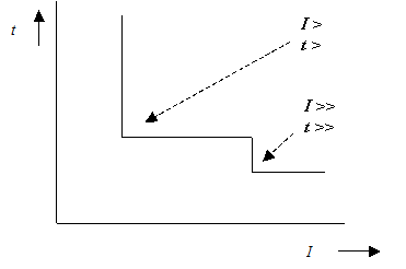
The characteristic of the fixed time protection is given in the diagram below. The characteristic is defined by one, two or three points. On the plot below a two point example is shown.
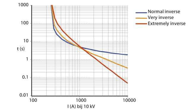
Inverse
The general form of the inverse characteristic is given in the diagram below. The final form of the curve is determined by the sort and the values of m, I> and, if specified, I>> and t>>.
The following parameters can be set for the protection devices above:
•Sort normal inverse, very inverse, extremely inverse
•I> current setting for the slow stage
•m time multiplier setting (TMS)
•I>> current setting for the medium stage
•t>> time setting for the medium stage
•I>>> current setting for the fast stage
•t>>> time setting for the fast stage
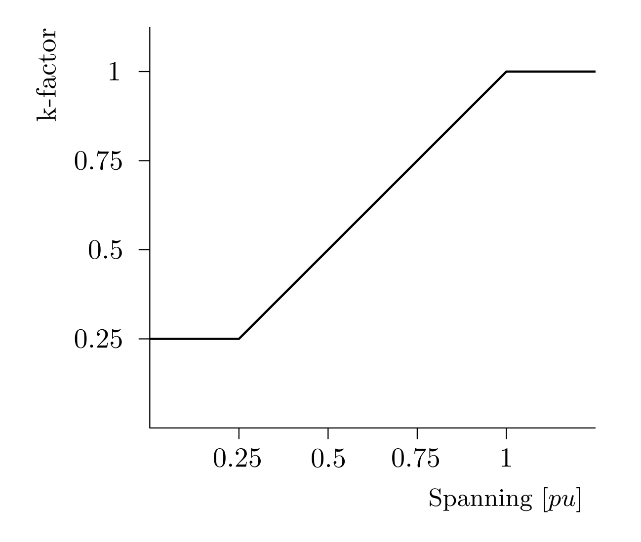
In case of a generator protection it can be necessary to make the time-current curve dependent of the voltage. This function can be selected by checking ‘voltage proportional’ checkbox. The k-factor in the equation below is determined using the following characteristic:
The inverse curve is calculated using the equation below:
Parameters of the inverse curve are given in the following table:
Characteristic |
α |
β |
Normal inverse |
0.02 |
0.14 |
Very inverse |
1 |
13.5 |
Extremely inverse |
2 |
80 |
Long time inverse |
1 |
120 |
The plots and equations for this sort of protection are standardized and described in IEC 60255-155. Besides these inverse curves there is RI-inverse curve available for older electromechanical relays, which can be calculated using the formula below:
If the current comes below the pick-up current value I> after the pick-up of the relay, then the relay reset will be started. The reset function of a relay can be an important criterion for protection coordination in case of fast repetitive faults (for instance, due to automatic re-closing of circuit breakers or re-closers). The reset function can be implemented in three ways, namely: instant, fixed time and time dependent. Most commonly use is the time dependent option (disc emulation). This option and the instant reset are implemented in Vision. The reset function is defined conform to the following IEEE formula with the k-factor:
Please pay attention that the reset time in the equation above is given including the m-factor (TMS). Suppose, for instance, that the reset time of a relay is given to be 9.7 s and the TMS is set to 0.3 s, then the total reset time, which should be set in Vision, is equal to: 9.7 x 0.3 = 2.91 seconds.
Special
The tripping characteristic can be specified by the user using the following formula:
The formula above is also known as the IEEE/IEC curve:
Characteristic |
α |
β |
c |
d |
e |
treset |
αreset |
IEC-A Normal/Standard inverse |
0.02 |
0.14 |
1 |
1 |
0 |
* |
* |
IEC-B Very inverse |
1 |
13.5 |
1 |
1 |
0 |
* |
* |
IEC-C Extremely inverse |
2 |
80 |
1 |
1 |
0 |
* |
* |
Long time inverse |
1 |
120 |
1 |
1 |
0 |
* |
* |
IEEE-D MOD Moderately inverse |
0.02 |
0.0515 |
1 |
1 |
0.114 |
4.85 |
2 |
IEEE-E VERY Very inverse |
2 |
19.61 |
1 |
1 |
0.491 |
21.6 |
2 |
IEEE-F XTRM Extremely inverse |
2 |
28.2 |
1 |
1 |
0.1217 |
29.1 |
2 |