The earth fault protection detects whether the sum of the three phase currents is unequal to zero. The input of the earth fault protection is the phasor sum of the three measured phase currents (Ia + Ib + Ic = 3I0), with zero sequence current I0 present only in case there is path to ground available. The earth fault protection is a part of the circuit breaker in Vision.
For earth fault protection a characteristic can be chosen. The procedure is the same as for the current protection.
Modelling
Characteristics
Details about different characteristics is to be found in current protection description.
Directional sensitivity
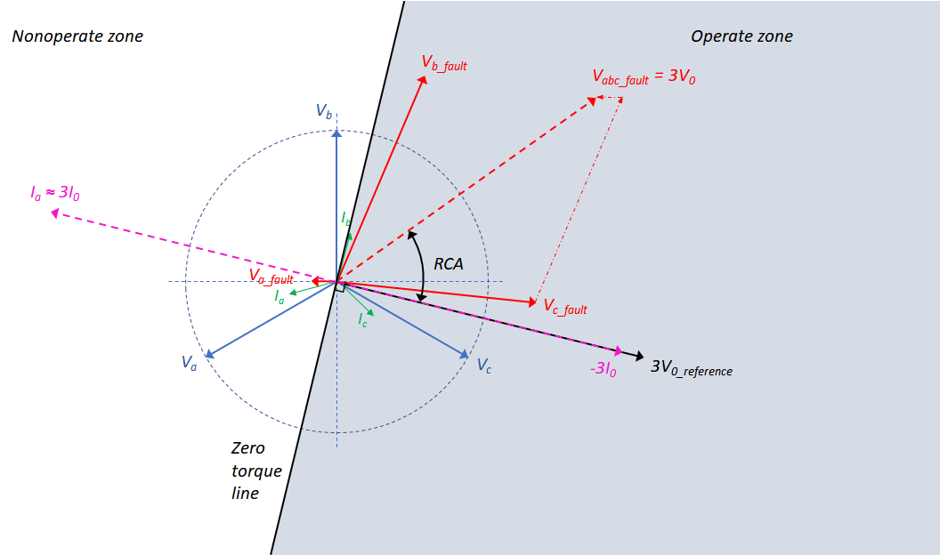
The directional sensitivity can be specified at general parameters of the circuit breaker. There the direction can be set as forward, backward or none (undirected). In case the protection is directional, the Relay Characteristic Angle (RCA) can be specified. The direction of a fault current as a result of an earth fault is determined based on the angle between this current and the reference. In the figure below an illustration of a phase to earth short-circuit in phase a in a distribution network earthed via an zigzag transformer is given. The undisturbed phasors of both the voltage and current are drawn in blue and green, respectively. In case of a low resistance fault to earth in phase a the neutral point shifts and the voltage phasor of the disturbed phase rotates. As a consequence of these events the voltages in undisturbed phases increase and their phasors also rotate. The fault voltages are shown in red. The voltage is measured using open delta measurement, the input of the relay is the sum of three voltage phasors (Ua + Ub + Uc), which is equal to 3V0.

To guarantee the reliability of directional operation the voltage phasor 3V0 (that serves as a reference for the detection direction) is rotated such that it comes in phase with the zero sequence current -3I0. This angle, RCA, is dependent on the zero sequence circuit and therefore has to be determined for each situation specifically. The location of the fault is determined by calculating the angle between the reference 3V0 and the zero sequence current 3I0. The maximum sensitivity of the relay is reached if the measured current is in phase with the reference phasor 3V0 rotated (maximum torque line).