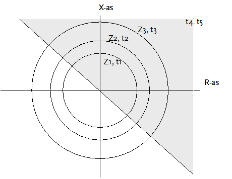
The distance protection measures the impedance in the direction of the feeder. There are three zones with forward directional sensitivity and one zone with backward directional sensitivity.
The distance protection is a part of the Circuit Breaker.
PARAMETERS
Parameter |
Default |
Unit |
Description |
Type |
|
|
Predefined type from component database |
Short |
|
|
Short name. Maximum 10 characters. |
t,input |
0 |
s |
Pickup time |
t,output |
0 |
s |
Operation output time |
|
|
|
|
Pickup |
|
|
|
Ie > |
0 |
A |
Earth current activation threshold value |
I > |
0 |
A |
Overcurrent activation threshold value (pick-up current) |
U < |
0 |
kV |
Undervoltage activation threshold value |
Z < |
0 |
Ohm |
Impedance zone activation threshold value |
|
|
|
|
Kn |
0 |
|
Factor KN for asymmetric short circuits: absolute value and angle |
|
|
|
|
Forward: |
|
|
|
Number of zones |
0 |
1/2/3 |
Number of zones (1, 2 or 3) |
t1, t2, t3 |
0 |
s |
First, second and third zone tripping time |
end time |
0 |
s |
Forward directional final tripping time |
|
|
|
|
Backwards: |
|
|
|
T |
0 |
s |
Reverse directional tripping time |
|
|
|
|
Undirected: |
|
|
|
end time |
0 |
s |
Undirected final tripping time |
Edit zone
Using the button Edit zone the characteristics of the three forward directional zones and the one reverse directional zone can be specified.
Parameter |
Default |
Unit |
Description |
Number of characteristic |
1 |
1/2 |
1: for all fault types the same characteristic 2: different characteristics for phase-phase fault and phase-ground fault |
Characteristic |
|
|
Circle / Mho / Polygon |
|
|
|
|
Circle: |
|
|
|
Z |
0 |
Ohm |
Circle radius |
|
|
|
|
Mho: |
|
|
|
Z |
0 |
Ohm |
Circle radius |
R |
0 |
Ohm |
Circle centre R-coordinate |
X |
0 |
Ohm |
Circle centre X-coordinate |
|
|
|
|
Polygon (max 5 lines): |
|
|
|
R |
0 |
Ohm |
R-coordinate of a point on the line |
X |
0 |
Ohm |
X-coordinate of a point on the line |
Direction |
0 |
degrees |
Slope angle of the line through the point R-X |
|
|
|
|
Circle
A zone can be characterized with a circle diagram. The forward-facing zones 1 and 2 are provided with auxiliary buttons with the default of 85% and 115% for filling in the impedance. These values can be adjusted by right-clicking on them. For zone 1 there is then a choice of 70, 75, 80, 85, 90 and 95%. For zone 2 there is then a choice of 105, 110, 115, 120, 125, 130 and 85 (+85 ')%.
With the 85% button at Z1, the value of 85% of impedance in the forward direction to the next node can be transferred to the input field of Z1.
With the 115% button at Z2, the value of 115% of impedance in the forward direction to the next node can be transferred to the input field of Z2.
85 (+ 85 ')% means: 85% of impedance in the forward direction to the next node + 85% of impedance of the shortest non-mesh cable from that node.
Mho
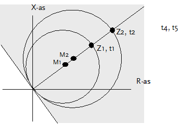
A zone can be characterised using a circle diagram of which the centre is moved in the R-X plane. The circle radius is indicated with the impedance Z and the centre with R and X (in Ohm).
Polygon
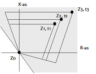
A zone can be characterised using a polygon. It is defined by 3, 4 or 5 lines, crossing each other in such a way that they enclose an area. Each line is defined with a point where it runs through and a slope (in degrees).
MODELLING
Three zones of the impedance relay have a forward measurement, one zone has a reverse measurement. The final zone has the possibility of only a forward directional measurement or also a reverse directional measurement. If the reverse directional measurement is not to be used, the corresponding tripping time (undirected end time) must have a value of 0.
Circle characteristic

The forward directional measurement only lead to a trip if the measured impedance is located in the grey shaded area in the above figure. The slope of the slanted line in the R-X diagram is -45 degrees.
The next table applies:
Measured impedance |
Action |
|Zm| < Z1 and Zm in grey area |
Trip on t = t1 s |
|Zm| < Z2 and Zm in grey area |
Trip on t = t2 s |
|Zm| < Z3 and Zm in grey area |
Trip on t = t3 s |
|Zm| > Z3 and Zm in grey area |
Trip on t = forward directed final time |
|Zm| < Zreverse and Zm not in grey area |
Trip on t = reverse time |
Zm not in grey area |
Trip on t = undirected final time |
For the zone impedances the following applies:
Z1 < Z2 < Z3
Mho characteristic
The forward directional measurement only lead to a trip if the measured impedance is located in the grey shaded area in the above figure. The slope of the slanted line in the R-X diagram is -45 degrees.
The zones are described by the circles, using the centre points (M1, M2) and their radii (Z1, Z2).

The next table applies:
Measured impedance |
Action |
Zm inside circle 1 and Zm in grey area |
Trip on t = t1 s |
Zm inside circle 2 and Zm in grey area |
Trip on t = t2 s |
Zm inside circle 3 and Zm in grey area |
Trip on t = t3 s |
Zm outside circle 3 and Zm in grey area |
Trip on t = forward directed final time |
Zm inside reverse circle and Zm not in grey area |
Trip on t = reverse time |
Zm outside reverse circle and Zm not in grey area |
Trip on t = undirected final time |
For the zone impedances the following applies:
Z1 < Z2 < Z3
Polygon characteristic
The forward directional measurement only lead to a trip if the measured impedance is located in the grey shaded area in the above figure. The slope of the slanted line in the R-X diagram is -45 degrees.
The zones are described by the polygons, using the lines through the points Z0, Z1, Z2, Z3 and the angles of their slopes.

The following table applies:
Measured impedance |
Action |
Zm inside polygon 1 and Zm in grey area |
Trip on t = t1 s |
Zm inside polygon 2 and Zm in grey area |
Trip on t = t2 s |
Zm inside polygon 3 and Zm in grey area |
Trip on t = t3 s |
Zm outside polygon 3 and Zm in grey area |
Trip on t = forward directed final time |
Zm inside polygon circle and Zm not in grey area |
Trip on t = reverse time |
Zm outside polygon circle and Zm not in grey area |
Trip on t = undirected final time |
For the zone impedances the following applies:
Z1 < Z2 < Z3
Measurement for diverse fault types
For asymmetrical phase to ground fault the factor KN is introduced. In those cases a zero sequence current I0 flows. The following applies:
or
where:
For a three phase fault:
For a two phase fault (e.g. phases b and c)
For a two phase to ground fault (e.g. with phases b and c)
For a single phase to ground fault (e.g. phase a)