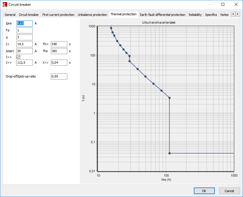
A thermal protection relay is usually applied to a motor in order to protect it against thermal effects. The relay generates a thermal equivalent of the machine as function of the positive and negative sequence component of the motor current. In this way both the stator and the rotor of machine are protected against overheating as a result of overloading or unbalance. Thermal protection is a part of a circuit breaker in Vision.
Parameters

Parameter |
Default |
Unit |
Description |
|---|---|---|---|
Ipre |
0 |
A |
initial loading current (loadflow result) |
Fa |
1 |
|
surrounding temperature factor |
q |
3 |
|
unbalance factor |
I> |
0 |
A |
pickup current of the relay, I> = Inom · k (k = 1 .. 1,5) |
Th> |
0 |
s |
thermal time constant, machine heating |
Istart |
0 |
A |
current at which it is assumed that the motor is starting |
Ths |
0 |
s |
thermal time constant, machine heating during start |
I>> |
0 |
A |
current setting for medium protection stage |
t>> |
0 |
s |
time setting for medium protection stage |
Drop-off/pickup ratio |
1 |
|
ratio of the drop-off current value to the pickup value (only applicable if I>> has been specified) |
MODELLING
The large variations in motors and their applications results in very complex thermal relations. It is therefore practically impossible to describe the thermodynamics of the motor exactly using a generic mathematical model. However, it is possible to consider the machine as a homogeneous mass and to represent its thermodynamics using first order differential equation. In time domain and solved for t as function of Ieq the following equation can be derived:
where:
t_trip(I_eq) |
trip time as function of the equivalent current |
|---|---|
I_eq |
equivalent current |
τ |
thermal time constant |
F_a |
surrounding temperature factor |
I> |
pickup current of the relay, I> = Inom · k (k = 1 .. 1,5) |
I_pre |
initial loading current (loadflow result) |
Using this equation the time-current characteristic can be plotted, which is used internally in the protection module of Vision. The thermal protection relay is afterwards treated as an current protection relay.
Machines are designed to operate at a specific surrounding temperature within a certain tolerance. If the real surrounding temperature is higher than the design temperature the windings can heat up more than the maximum temperature even if the machine operates within its loading limits. The thermal loading characteristic can be adjusted for a deviation in the surrounding temperature using the Fa coefficient. This coefficient is determined as follows:
where:
F_a |
surrounding temperature factor |
|---|---|
T_max |
maximum machine temperature conform IEC 60085 |
T_a |
actual surrounding temperature |
T_limit |
maximum surrounding temperature, for which the machine is designed |
Unbalance in the stator windings of the motor results in an additional production of heat in the rotor of the machine. This heating is not considered in the thermal loading characteristic. To take into account the effect of unbalance the equivalent current is used. This current can be determined as follows:
where:
I_eq |
equivalent current |
|---|---|
I_1 |
positive sequence current component |
I_2 |
negative sequence current component |
q |
unbalance factor |