An object can have multiple graphic representations on different sheets. This makes it is possible to represent a specific group of objects on one sheet, to keep a good overview of the important objects in a large network. Links and cables which connect the nodes on two sheets do not have to be represented on each of these sheets. Nodes can be always represented on several sheets. Elements and branches can only be represented together with their associated nodes.
Each object, always remains a unique object in the network model, independent of the number of graphical presentations. Modifying the technical model parameters of a specific object is possible from all the graphic presentations of that object. The graphic parameters (form, size, colour, etc.) of a specific object can vary between sheets and can be established independently for all presentations of the object.
A new presentation of an object is created by first selecting that object on a certain sheet and then pasting it graphically on another sheet by using Start | Edit | Represent | Selected objects at sheet ... . Hereafter the graphical properties of the represented object can be modified. Each object can only be presented once per sheet.
The status 'selected' is a property of an object. As a consequence, selecting an object on one sheet, selects the object on all sheets where it is graphically represented. All presentations of an object are therefore selected at the same time or not selected at all.
The status 'removed' is linked to the object presentation. Thus the object will only be removed after all presentations are removed.
Objects with multiple presentations can be easily distinguished in the network by altering their colours through View | Appearance in Edit mode | Colour, Multiple presentation
In case a node has multiple representations, the sheet names the node is represented on can be shown through an user-defined view
Example
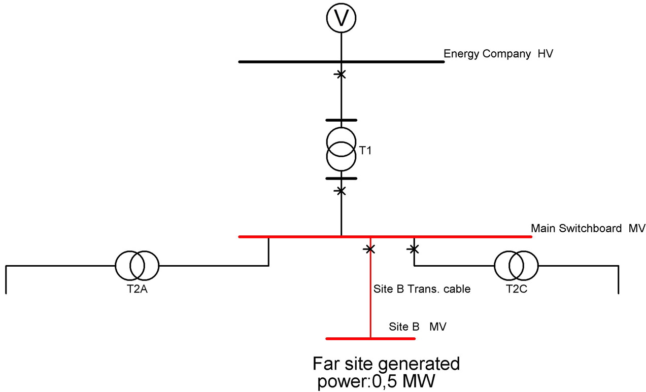
The next example shows a network, modeled on two sheets: "General plan" and "Far site". The node "Main Switchboard MV" feeds the node "Site B" (plus the network downstream) through the transformer "Site B MV transf". These objects are marked in red on the sheet "General Plan". The other network components and the network source are shown in black.

Sheet "General plan"
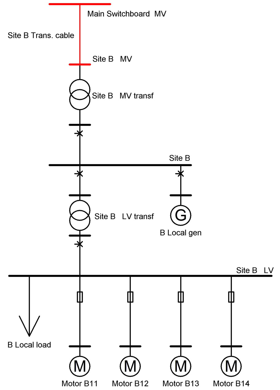
The details of site B are presented on sheet "Far Site". The nodes "Main Switchboard MV" and "Site B" have a presentation on this sheet as well and are also marked in red.

Sheet "Far site"