A node represents a rail.
PARAMETERS
General
Parameter |
Default |
Unit |
Description |
Name |
|
|
Name of the node |
Unom |
Unom 1) |
kV |
Rated voltage |
Simultaneousness |
1 |
|
Simultaneousness factor of the connected loads |
ID |
2) |
|
Identification |
Short Name |
|
|
Short name |
Function |
|
|
Function |
1) On exiting a node form via OK, Unom is saved as the default value
2) On exiting a node form via OK, a warning will appear if the ID is not unique
Name
Preferably a different name should be chosen for each node.
ID
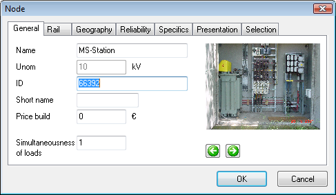
In addition to the name, the ID (consisting of a maximum of 25 characters) can be used to identify a node. This ID is also used when importing or exporting network data.
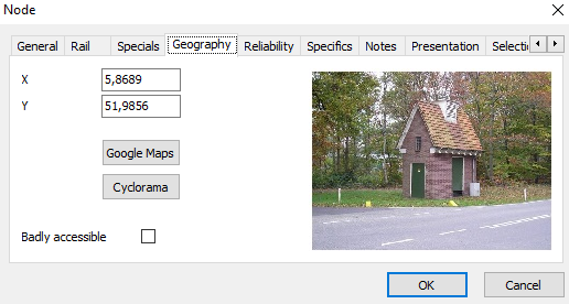
In the node form, the Geography tab shows a picture of the station if ID.jpg or ID\ID.jpg or Regio\ID.jpg or Regio\ID\ID.jpg matches the name of a jpg image file in the folder with station images specified in the Options under File locations | Pictures. Clicking on the image opens it with the default program in Windows.
In the node form, the General tab displays a series of images if ID_*. Jpg or ID\*. Jpg or Regio\ID_*. Jpg or Regio\ID\*. Jpg matches the name of a jpg image file in the folder with station images specified in the Options under File locations | Pictures. The asterisk (*) in the reference to the jpg is a wildcard symbol. You can use the arrow buttons to browse through the images. Clicking on the image opens it with the default program in Windows.

Unom
Unom indicates the nominal operating voltage (for example 380 kV, 110 kV or 10 kV). This Unom can be changed as long as the node is not connected to another node.
When leaving a node with OK, Unom is saved as default value.
There is a possibility to collectively change the nominal voltage of multiple nodes. If the nodes are connected to each other by means of cables, connections, reactance coils or links, it is only possible to change the Unom of all connected nodes simultaneously via Start | Edit | Collective | Node. If the nodes are connected by transformers, the rule applies that the nominal voltage of transformer winding and node may not deviate more than 20% with respect to each other.
Simultaneity
For each node a simultaneity factor can be specified with which all the (transformer)loads (P and Q) connected to the node are multiplied.
See also: Simultaneousness
Rail
Parameter |
Default |
Unit |
Description |
Type |
|
|
Busbar type |
Unom |
0 |
kV |
Rated voltage (not for calculation) |
Inom |
0 |
A |
Rated current |
Ik dynamic |
0 |
kA |
Admissible dynamic short-circuit current |
Ik thermal |
0 |
kA |
Admissible thermal short-circuit current |
at |
1 |
s |
Duration of defined admissible thermal short-circuit current |
Type
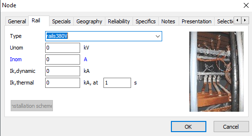
In the node form on the tab Rail, a picture of the rail type will be shown if railtype.jpg or railtype_*.jpg or railtype\*.jpg matches the name of of a jpg file in the Types directory, defined in the Options, at File locations | Pictures. By clicking on the picture, it will be opened with the default Windows viewing program.
In the node form on the tab Rail, the button Installation scheme will open one or multiple pdf files if ID\*.pdf of Regio\ID\*.pdf matches the name of a pdf file in the Stations directory, defined in the Options, at File locations | Pictures.

Dynamic short-circuit current
The mechanical (dynamic) forces on the installation at the node are determined by the peak short-circuit current (Ip). This current is calculated by the IEC 60909 calculation. The result is compared with the admissible dynamical short-circuit current. This is reflected in the colour indication.
Thermal short-circuit current
The thermal stress on the installation at the node is determined by the sub-transient short-circuit current (Ik"). This current can be calculated by both the IEC 60909 calculation and by the Fault Analysis calculation. The result is compared with the admissible thermal short-circuit current. From this, the maximum short circuit duration (tmax) is calculated.
Diverse
Installation
The data of the installation is only required when performing the arc flash calculation.
Parameter |
Default |
Eenheid |
Omschrijving |
Type |
|
|
|
Solidly earthed |
not |
|
|
Conductor gap |
|
mm |
|
Working distance |
|
mm |
|
Enclosed position |
not |
|
|
Arc flash protection |
not |
|
|
Electrode configuration |
|
|
|
H |
|
mm |
Height |
B |
|
mm |
Width |
D |
|
mm |
Depth |
Kb |
|
|
|
Kp |
|
|
|
Kt |
|
|
|
Feeders
The feeders of a node can be defined on this sheet. The order must correspond to the real order of the feeders on the rail structure.
Parameter |
Default |
Unit |
Description |
Name |
|
|
Name of the feeder |
Sort |
|
|
Type of the feeder |
To |
|
|
Indication of the direction of the branch in the feeder |
Type |
|
|
Type for the arc flash calculation |
Conductor gap [mm] |
|
mm |
The conductor gap, in case this differs from the rail conductor gap |
Electrode |
|
|
Horizontal/Vertical; Closed/Open |
H [mm] |
|
mm |
Height of the compartment |
B [mm] |
|
mm |
Width of the compartment |
D [mm] |
|
mm |
Depth of the compartment |
Information |
|
|
Additional information |
Ripple control source
The ripple control calculation allows for the calculation of the propagation of ripple control signals in the network. See: Harmonics. One or more ripple control sources of different frequencies can be inserted into the network.
Parameter |
Default |
Unit |
Description |
Frequency |
0 |
Hz |
Frequency of the ripple control signal |
Voltage |
0 |
% |
Relative voltage of the ripple control signal with respect to the nominal voltage |
Angle |
no |
degree |
Angle of the ripple control voltage with respect to the loadflow voltage |
External neutral point grounding
A node may have an external grounding connection. This can serve as a common grounding point for the star-points of several components. For example, the star-points of synchronous generators, synchronous motors, capacitor, shunt coil or transformer can be commonly grounded. This has consequences for the short-circuit calculation with ground connection. In this tab the grounding impedance can be specified.
If one of the connected elements uses the external grounding connection, it should be defined at the Connection tab of the concerning element.
Customer
These are informative data about a possibly customer.
Rail differential protection
This is a rail differential protection. All involved circuit breakers has to be mentioned and all involved circuit breakers will also switch off in case the protection is tripped.
There is no correction for direction and ratio: the sum of the currents has to be zero during normal operation. For the detail working see Differential protection.
Limits
The voltage control can be turned off or there can be alternative limits.
Icon
A short text can be displayed in a point symmetrical form near the node in the diagram. Text, text color, background color, shape and size are adjustable.
Gaia
A Gaia network of the node can be opened in Gaia. The name of the gnf must match the ID of the node. The root of the Gaia network files must be entered in the options at File Locations, Specific. In this directory, sub-directories are allowed.
If an IEC 60909 calculation has been performed, the calculated symmetric short-circuit currents are written or updated in the short-circuit currents.txt file.
If there is a node in the Gaia network with a name and / or ID from the short-circuit currents and there is a power supply, then the Ik "nom is set to the value from the file.
Geography
Parameter |
Default |
Unit |
Description |
X |
0 |
degrees |
Geographical X-coordinate |
Y |
0 |
degrees |
Geographical Y-coordinate |
Badly accessible |
no |
|
Rather don't visit station (normal open point optimization) |
By specifying the geographical coordinates, the object can be presented on a geographical layer or in a geographical application. See: Geography.

Using the button Google maps, the station geographical location will be presented using the default web browsers through the web-application Google maps.
Reliability
Parameter |
Default |
Unit |
Description |
Failure frequency |
0 |
per year |
Mean number of occurrences that the node fails (short circuit) |
Repair duration |
0 |
minutes |
Mean duration of repair or replacement |
Maintenance frequency |
0 |
per year |
Mean number of occurrences that the node is in maintenance |
Maintenance duration |
0 |
minutes |
Mean duration of maintenance |
maint. cut-off duration |
0 |
minutes |
Mean duration of cancellation of maintenance in case of emergency |
Remote status indication |
no |
yes / no |
Presence of remote node status indication |
The remote status indication influences the time to signal a fault (short/long).
MODELLING
Load flow and fault analysis
For all loads present at a node, the load is corrected by the simultaneousness factor for load flow calculations and sequential fault analysis.
Pload,calculation = Simultaneousness * Pload
Qload,calculation = Simultaneousness * Qload
The values of Pload and Qload are determined from the scaling and growth factors from the growth :
Pload = Pspecified * Scale factor(year) * f(growth, year)
Qload = Qspecified * Scale factor(year) * f(growth, year)
IEC 60909
As loads are not taken into consideration in an IEC 60909 calculation, the simultaneousness factor is not applicable when performing this calculation.
The ratio Ik"/Ik,max is used for the colour indication.