For most loadflow calculations a minimum of one external grid must be present in the network. Several external grids are possible, but might give an unreliable results if they are connected through network components.
Prior to each calculation, Vision carries out an island test, and network components and network sections which are not linked to a source or an generator with power frequency droop are shown in the island colour after completion of the calculation. See: Island mode
Load flow
A load flow calculation is carried out as follows:
•choose Calculate | Calculate | Loadflow
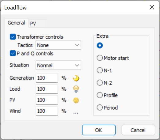
•specify loadflow settings
•exit form via OK

Using the F9 key the previous calculation is repeated with the specified settings.
Settings
The following parameters can be set for a load flow calculation.
Transformer controls
Transformers with voltage control can be "switched off" for a calculation. In this case, the value is used as indicated in the transformer form for the calculation. This can also be the calculated tap setting from of a previous load flow calculation.
If Vision has adjusted the tap settings during a calculation, the control actions of the relevant transformers are indicated in a list, with the question whether these tap settings should be adopted. With Yes, the tap settings are adjusted on the transformer form. With No, the new tap settings remain the "runtime" tap settings. A subsequent load flow will start from these "runtime" tap settings. Only after a change in the network the runtime tap settings are initiated again to the input tap positions.
P and Q controls
Shunt controls (e.g. capacitors) can be deactivated for a calculation. In that case, the shunt element is switched on.
P and Q controls of loads, PVs, wind turbines and batteries can be "turned off" during a calculation. However, the respective elements are initialized according to their control, with a default voltage of 1 pu or a default current of 0 pu as input.
Motor start
A starting motor causes a voltage dip in the network, which can be estimated using a load flow calculation. During the motor start the starting of the motors in the network is modelled with their short circuit impedance. The external grids and synchronous generators are modelled as equivalent voltage sources behind their sub-transient impedances.
After selecting motor start, the starting motors can be selected on the motor start tab.The results are displayed for three different calculations:
1 situation without selected motors
2 situation with selected motors starting (where the eventually chosen scenario is (also) active)
3 situation after motor start (with started motors)
Whenever a motor start is performed, all selected motors will be started together.
N-1
Calculation of the loadflow, where a single object is not available. After selecting n-1, the unavailable objects can be selected from the n-1 tab.
N-2
After selecting n-2, the loadflow is performed with all possible combinations of two objects which are unavailable. The objects to be considered can be selected in the n-2 tab.
Profile
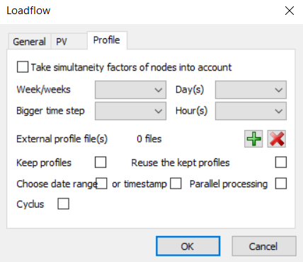
A profile specifies the load or generation for a number of consecutive time steps. A possible application is a daily load profile. The specified load or the generated power is multiplied by the factors recorded in the profile. Multiple load flow calculations are therefore performed, depending on the setting on the Profile tab. The profiles are processed in the calculation and the result can be reported for all the calculated time steps.
There are two ways to work with profiles:
•Profile: in Vision defined profile, stored in the network file.
•External profile: external Excel file which can be loaded for the profile loadflow calculation.
An external profile can be selected in the profile tab

If the Cyclus box is checked, then a further analysis is done for the cables and transformers in the network based on their temperature properties. This cyclic calculation is based on norms IEC 60853 and IEC 60287 (for the cables) and IEC 60076-7 (for transformers). The graphical representation of the results can be found by clicking on the 'Cyclus' button present in the Details window of each cable and transformer.
Year
The choice of a year, with which the (transformer) loads get a different value through growth (filled in at Growth), can be set at the network level. By choosing a year, in the Ribbon Start | Time | Year, the loads in the network are set to a value corresponding to the load growth. With this value all calculations can now be performed.
Introduction of Inom' and Snom' for branches
For all branches the variables Inom' and Snom' have been introduced for a uniform overload indication in the load flow. For a cable the value of Inom' is obtained from the weakest cable part input data. For a connection the value of Inom' is obtained from the input data, in conformance with the options. For the other branches the values of Inom' and Snom' are obtained from the input data. All values are obtained as follows:
•Link: Inom' is set to infinite or to a user specified value.
•Cable: Inom' is set to the weakest cable part Inom(G) x rerating factor. G refers to the chosen soil heat resistance.
•Connection: Inom' is set to either Inom1 or Inom2, according to the options settings in: Application menu | Options | Calculation | General.
•Reactance Coil: Snom' is set to the Snom input
•Transformer: Snom' is set to the Snom input or to the special input (formerly Smax)
•SpecialTransformer: Snom' is set to the Snom input or to the special input (formerly Smax)
•Three windings transformer: Snom1', Snom2' and Snom3' are set to the Snom inputs or to the special inputs (formerly Smax)
Load flow convergence
The Newton-Raphson method is used to calculate the load flow. This method follows an iterative approach to obtain a solution, where in each iteration a derivative of the state of the network is used to determine the next state of the network. The Newton-Raphson method is widely used and is known for its computational speed and good convergence properties.
Nevertheless, it can sometimes happen that no solution is found. The message is given here: "maximum number of iterations reached" or "solution diverges". Networks where a solution diverges often have connections with relatively high impedances in combination with relatively large loads. It could also be that an input error has been made. For example, a kilo / mega-error makes the capital sometimes a thousand times too large.
There are various ways of detecting errors and getting a better loadflow convergence.
To detect errors:
•Check the network via Bestand | Prepare to check whether there are anomalies in the network. Large element capacities are reported.
•Let elements be drawn as circles via View | Display in Edit mode Symbol, Power. If almost all the circles are very small, there may be an input error with the biggest circle.
To force the load flow:
•Reduce the load and/or generation percentage in the load flow settings.
•Collect the load behaviour of all (transformer) loads collectively at constant impedance.
•Switch off a power supply by opening a switch
•Put Sbase in the options successively on 1, 10 or 100 MVA.
•Increase the link impedance in the options.
•Adjust the advanced load flow options in the options.
If the load flow can be solved, it is important to look at overload and over- and undervoltage. Probably there are problems with large loads and/or small branches in the vicinity of these objects.
Load flow control parameters
The loadflow calculation follows an iterative process. The process stops when a sufficient accuracy has been reached. The process also stops when the solution does not converge. In that case a message will be generated. The cause of such an event is difficult to predict. One of the possible causes is an incorrect value of Sbase.
A number of control parameters has been defined for the experienced user, to obtain more information about the solution process and to control the accuracy.
Debuglevel
Feedback level about the iterative loadflow process.
Default is: 0.
0 |
No extra information |
1 |
General information and error codes Warning at increasing power mismatch |
2 |
Per iteration the name of the node with the largest power mismatch plus its power mismatch and voltage |
3 |
Per iteration for all nodes: power mismatch and voltage |
Max. number of Newton-Raphson iterations
Indicates The maximum number of iterations in the Newton-Raphson process.
Default is: 15.
Precision
Accuracy of the Newton-Raphson process. This is the maximum allowed power mismatch in p.u.
Default is: 10-5 p.u.
Divergence factor
Factor indicating the maximum increase of the power mismatch between two successive iterations.
Default is: 100.
See also: