Apart from the internal profiles, a load flow calculation can also be executed using an externally generated file of time related factors for loads, generators and batteries. Also transformer tap settings can be influenced by an external profile. The external profiles can be defined using Excel. They may be generated from measurement data or other external sources. The external profile can be activated on the tab Profile of the load flow calculation settings.
Unlike the profiles, the external profiles have a strict relation to the time. The time stamps (date and time) and the factors for consumed or generated power are linked in the file records. The actual power can be given as an factor of the elements nominal power or as absolute values, both as function of time. The ratio of active and reactive power is fixed.
The external profile is leading with respect to the built-in profiles and other settings. Each element with external profile data will be evaluated according to the external load data in the load flow calculations and internal profile data of that element will not be used.
Each element with no external profile data will be evaluated according to the attribute specifications in Vision. The next applies:
•If the default profile (only constants values of 1) is used, the actual value of the load is constant.
•If a time related internal profile is used, the profile values will be tuned to the external profile time stamps. Values will be interpolated to fit between the external profile's time stamps.
•If a free (not time related) profile is used, the calculation will not execute, because time related and free profiles do not mix.
Definition
An external profile has a header and value records. The header record is located at the first row of the spreadsheet. The value records are located from the second row onwards.
Header record
The header record consists of the definition of date and time and the specification of the element names. The date and time can be defined together in one column or in two separate columns.
•Date and time: the first column header has the text "Date & Time" or "Datum & Tiijd". The following columns are indicated by <NodeName>.<ElementName>, so separated by a point. If <NodeName> or < ElementName> is an asterisk, then this corresponds to each name, which allows a profile to be linked to multiple elements at once. The <NodeID>.<ElementName> notation can also be used.
•Date: the first column is indicated by the text "Date" or "Datum". The second column is indicated with the text "Time" or "Tijd". The following columns are indicated by <NodeName>.<ElementName> or <NodeID>.<ElementName>.
•Because a transformer load can contain three items, an addition can be made in the header: <NodeName>.<Transformer Load Name>.Load or <NodeName>.<Transformer Load Name>.Generation or <NodeName>.<Transformer Load Name>.PV.
•For the definition of a column for transformer tap settings, the column should be headed with <Transformer Name>.
Optionally, the units that apply to the values can be included in the second row. If no units are specified, the values below are interpreted as factors of the set element values. The identified units are: V, kV, A, A, VA, kVA, MVA, VA, KVA, MVA, W, kW, MW, W, kW, MW, var, kvar, Mvar, var, kvar, mvar, m/s, pu,%, ‰ and percentage points. The unit must correspond more or less with the requested value for a particular component type. A minus at the end of a unit means that the values should be applied with the opposite sign.
Value records
•Date and time together: the column is filled with an ascending range for date and time.
•Date and time separated: the first two columns are filled with an ascending range for date and time.
•Factors: each value column (with element name header) contains the factors to calculate the actual power for the corresponding element on the specific time stamp. The factors may be positive and negative.
•For transformer tap changers, the column contains the absolute tap changer setting.
The range of the value records does not need to be closed with a special marker. After the last value record, the spread sheet must be empty.
Example
The next network contains the elements “Load1” and “Load2”, both connected to the node “Node2”.

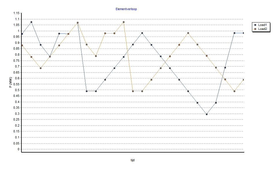
In this example, the external profile defines the factors for the powers of both loads, on a certain date, from 12:00 h to 18:00 h. The external profile can be defined on two ways, depending on the choice of the time stamp format:
Method 1:
date & time |
Node2.Load1 |
Node2.Load2 |
15-8-2011 12:00 |
1 |
0.9 |
15-8-2011 12:15 |
1.1 |
0.8 |
15-8-2011 12:30 |
0.9 |
0.7 |
15-8-2011 12:45 |
0.8 |
0.8 |
15-8-2011 13:00 |
1 |
0.9 |
. . .
|
||
15-8-2011 17:00 |
0.3 |
0.8 |
15-8-2011 17:15 |
0.4 |
0.7 |
15-8-2011 17:30 |
0.7 |
0.6 |
15-8-2011 17:45 |
1 |
0.5 |
15-8-2011 18:00 |
1 |
0.6 |
Method 2:
date |
time |
Node2.Load1 |
Node2.Load2 |
15-8-2011 |
12:00 |
1 |
0.9 |
15-8-2011 |
12:15 |
1.1 |
0.8 |
15-8-2011 |
12:30 |
0.9 |
0.7 |
15-8-2011 |
12:45 |
0.8 |
0.8 |
15-8-2011 |
13:00 |
1 |
0.9 |
. . .
|
|||
15-8-2011 |
17:00 |
0.3 |
0.8 |
15-8-2011 |
17:15 |
0.4 |
0.7 |
15-8-2011 |
17:30 |
0.7 |
0.6 |
15-8-2011 |
17:45 |
1 |
0.5 |
15-8-2011 |
18:00 |
1 |
0.6 |
Result of the load flow calculation:
