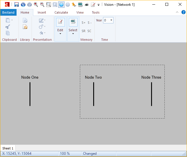
Between nodes Node Two and Node Three a cable connection will be added. This can be done after the two nodes have been selected. To select the two nodes, draw a rectangle while holding down the left mouse button.
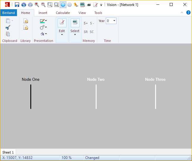
After releasing the left mouse button, the two nodes are selected. This is shown by the white colour of the nodes.
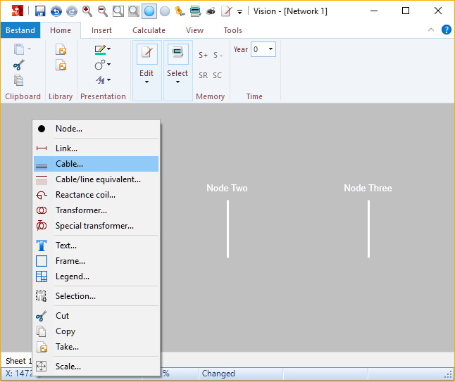
Now the cable can be added by right clicking on the workspace. A pop-up menu will appear with multiple choices. On the pop-up menu choose Cable.
The Cable input form pop-up. On the first tab general information like the Name of the cable, the Cable type and the Cable length can be specified.
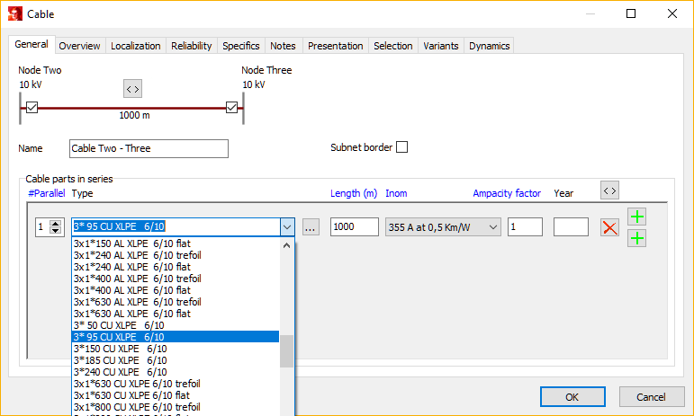
The cable type data will be specified using the pull-down menu. In this example a 3x95 Cu XLPE 6/10 kV cable will be used. The detailed cable data can be examined and altered using the button …. The length of the cable should be specified and is 1000 m in this tutorial. The cable ampacity is 355 A for the chosen ground specific heat resistance of 0.5 Km/W. An ampacity factor of 1 has been chosen. The form can be close by pressing OK.
The input form is closed by pressing the OK button.
As a consequence the cable has been inserted between the two selected nodes.
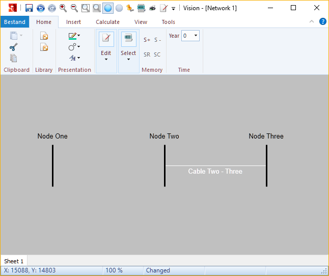
Hereafter, a transformer will be inserted between the left two nodes. To do this, only the two left nodes should be selected. First, to de-select any other objects, click with the left mouse button on a free spot on the worksheet. Secondly, draw a rectangle around the left two nodes (hold down the left mouse button). Hereafter the nodes Node One and Node Two should be selected. Subsequently click with the right mouse button on the workspace. A pop-up menu appears, where one can choose to add a Transformer.
Hereafter, the Transformer input form pops up. On the first tab, specify the name, for example Trafo 1.
On the Transformer tab specify the name plate data, for example:
•Snom: 100 MVA,
•uk: 10 % and
•Pk: 10 kW.
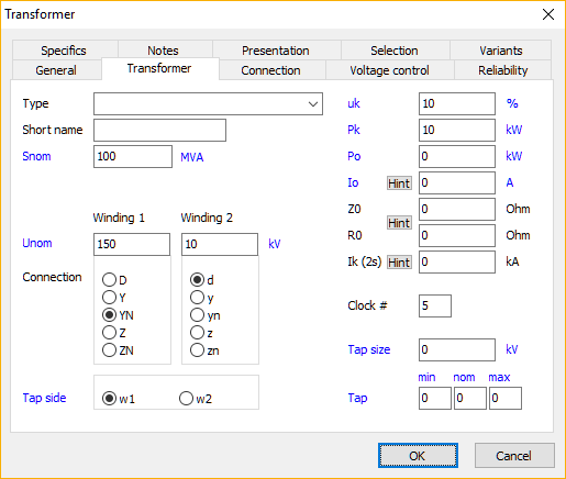
The rated primary and secondary voltages have been specified by default. These values can be altered if needed. The input form can be closed using OK.
The next step is Adding an external grid and loads.