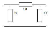
The harmonics modelling for higher frequencies affects the network models of cables, lines, transformers and all elements. The harmonic current injection has been modelled as part of a network load.
The harmonic calculation follows two consecutive steps:
•initial load flow calculation, determining the complex voltages for the base frequency
•calculation on the linearised system for all harmonic frequencies.
The next components harmonic behaviour will be described briefly:
•cable and line
•transformer
•three windings transformer
•network source
•load
•capacitor
•filter
•coil
•synchronous generator and motor
•asynchronous generator and motor
Cable and line
The cable and overhead line have been modelled using a long line (distributed parameter) model.

In these equations Zc represents the characteristic impedance and θ represents the characteristic angle:
With:
R : resistance in Ohm/km
L : inductance in H/km
G : shunt resistance in S/km
C : capacity in F/km
l : length in km
h : harmonic order number
ω : base frequency in rad/s
If C = 0 then the impedance will be calculated as: Z(h) = R + jhX.
The admittance matrix elements follow from:
y1 = y2 = Y1 / Ybase = Y1 ⋅ Zbase [pu]
y12 = Y12 / Ybase = Y12 ⋅ Zbase [pu]
The admittance matrix elements for reactance coils are:
Transformer
The winding configuration and an optional phase shift are included in the complex turns ratio. The clock number is an integer number from 0 to 11, representing the winding configuration effect. The phase shift has been specified in degrees. The next equations apply for a transformer with a tap changer on the primary side.
The normal system impedance follows from:
Three windings transformer
The model is similar to the normal transformer model.
Network source
The network source has been modelled as a constant voltage source behind a short-circuit impedance. The reactance is a function of normal reactance and frequency.
Load
The load is a combination of a harmonic source and a harmonic impedance. There are many ways to model the harmonic load. The chosen model reflects a typical domestic load.
Zload(h) = R50 + jhX50
Yload(h) = 1 / Zload(h)
Where:
The load has been taken as absolute values, always resulting in a positive impedance.
In the per-unit method:
The harmonic impedance can be included or excluded into the calculations. Excluding the impedance gives a "worst case" result.
Capacitor
The capacitor is a shunt element. Its admittance is calculated from the capacity.
Passive filter
The capacitor bank can be integrated in an R-L-C filter. In order to do so, the filter frequency and the filter quality factor have to be specified. The capacitor size is already specified in Mvar or in μF. The induction and the resistance follow from the filter frequency and the quality factor.
From the capacitor reactive power at nominal frequency (Qc) the reactance at base frequency will be calculated:
With hf the quotient of filter frequency and rated system frequency.
The coil reactance at nominal frequency is:
The resistance will be calculated from the quality factor q (mostly between 20 and 30).
The filter admittance for a harmonic frequency of order number h is:
Active filter
An active filter is used for compensation of harmonic currents in certain branch, element or three winding transformer. Active filter can be specified in Vision inside. Before adding the capacitor a measurement point has to be selected first. Further, the measurement point has to be specified from the list. It indicates where the compensation of harmonic currents is desired.
Percentage of compensation can be specified for each harmonic separately. 100% means that the current via the measuring point for this harmonic is fully compensated by the filter.
Active filter is used in Vision only for harmonic loadflow calculation. First, the harmonic loadflow without active filter is executed. In this manner the harmonic currents via measurement point without the compensation are calculated. After that, necessary current injections of the filter are determined and the harmonic loadflow is executed for the second time. The results are the harmonic voltages and currents in the network with the compensation using active filter.
Coil
The coil is a shunt element. Its admittance is calculated from its induction. The admittance is:
Synchronous generator and motor
The synchronous machine is a load for harmonic frequencies. The model is:
Where rgen,50 equals the fictive generator resistance, used in short-circuit calculations. The reactance xgen,50 is not the same as the saturated sub-transient reactance (xd"sat), used by the short-circuit calculations, but the normal sub-transient reactance xd".
Asynchronous generator and motor
The asynchronous machine model follows from:
Where:
RM : total motor resistance with the rotor locked
a : 0.45
b : 0.55
The machine impedance for harmonic frequencies follows from:
Positive systeem:
Negative systeem:
And the reactance:
See also: