The harmonics module gives insight in the behaviour of the flows and voltages at higher frequencies in the network. Two functions have been made available: the harmonics load flow and the calculation of the impedance spectrum.
•With the harmonics load flow the consequences of injected harmonic currents on the harmonic voltages and the harmonic distortion can be studied.
•With the impedance spectrum the possible resonances in the network can be analysed.
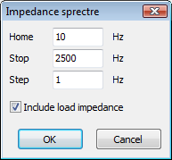
For both harmonic load flow and impedance spectrum calculations the load impedances can be specified to be included or not, by checking "Include load impedances".
Harmonic load flow
The harmonic calculation follows two consecutive steps:
•initial load flow calculation, determining the complex voltages for the base frequency
•calculation on the linearised system for all harmonic frequencies.
Starting the calculation, the user may specify that the results should be verified to a norm for maximum values of the harmonic voltages. These norms are defined in Types.xls.
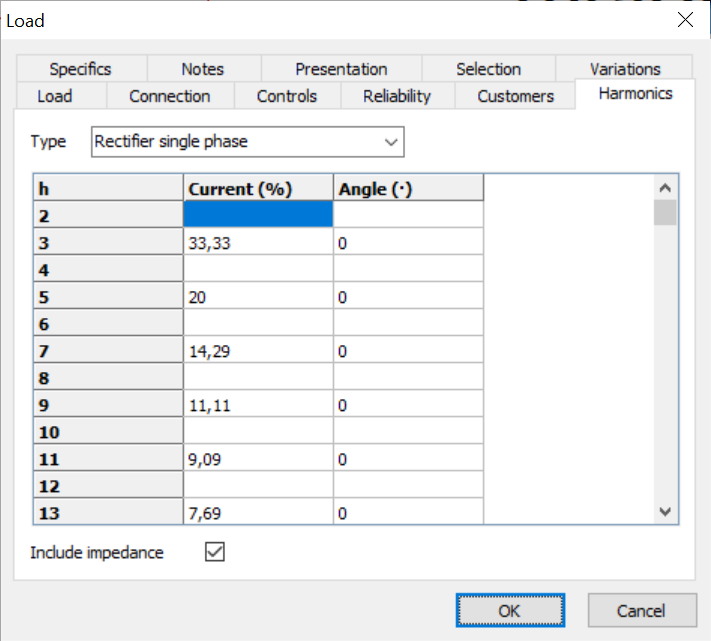
Non-linear components are harmonic sources for the network. The harmonic load flow will be calculated only if harmonic sources have been specified. The non-linear sources have been modelled as current injections, specified with the loads.
Next diagram shows the harmonic currents for a rectifier. The harmonic currents are a function of the harmonic order number.
I(h) = I50Hz / h
The harmonic currents have been specified as percentages of the rated load current at rated frequency and rated voltage.

All injection currents are injected with reference to the basic (50/60 Hz) load flow voltage angle. The harmonic load flow is evaluated for all specified frequencies.
Impedance spectrum
With the impedance spectrum the possible resonances in the network can be analysed. The impedance spectrum calculates the nodal impedance as function of the frequency. The complex impedance will be calculated for all frequencies between the start and stop frequencies.

The impedance spectrum will be calculated for all selected nodes.
Ripple control
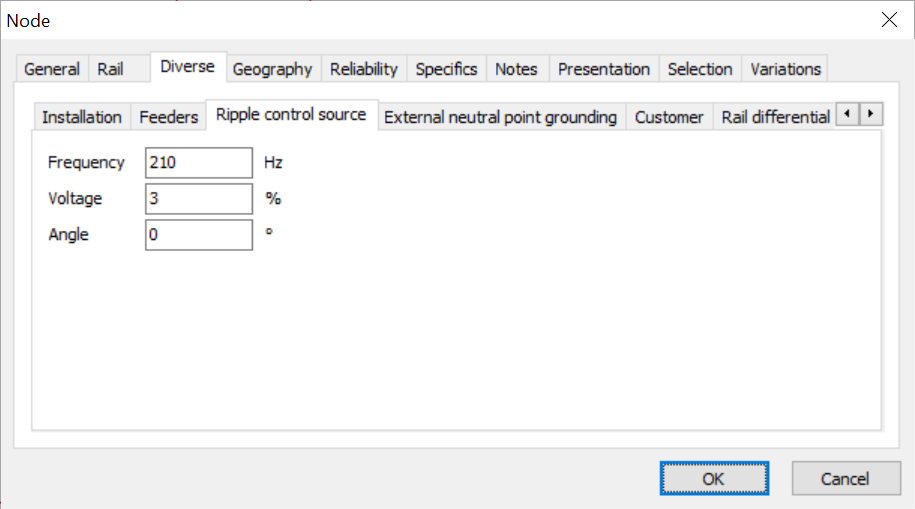
The ripple control calculation evaluates the control signals propagation in the network. One or more ripple control sources of different frequencies can be modelled. A ripple control voltage source can be defined on the tab 'Specials' of a node input form. The attributes are:
•Frequency: ripple control source signal frequency (Hz)
•U: ripple control voltage, relative to the rated voltage (%)
•Angle: ripple control voltage angle, relative to the actual voltage (degrees)

The calculation uses the normal sequence network and calculates the ripple control voltages throughout the whole network. The results are presented graphically and in tables.
The calculation either uses the standard load model or a frequency-independent load model.
•In the standard load model the reactance is linearly dependent of the frequency:
Zload(h) = R50 + jhX50
with:
R50, X50: load impedance at rated frequency.
•In the frequency-independent load model the impedance is as follows:
ZTF = U2 / (KN ⋅ S)
Zload(h) = ZTF ⋅ ( cos(FN) + j sin(FN) )
with:
KN: load factor, considers the simultaneous change (reduction or increase) of the power (real and reactive) of all loads in the network
FN: load angle, in degrees (0 degrees is pure real impedance, 90 degrees is pure inductive load)
U: load flow voltage (kV)
S: apparent power (MVA).
See also: