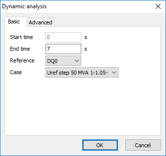
A dynamic calculation can be started using Calculate | Dynamic analysis.

In the form the parameters of the dynamic simulation can be specified.
Basic parameters are the start and the end time of the calculation and the dynamic case.
Also it is possible to choose between DQ0 and ABC reference. DQ0 reference is in general faster than ABC (especially in case the end time of the simulation is large), but less suitable for unbalanced events. DQ0 reference is a good choice for the modelling of the following dynamic events:
•start of an induction motor;
•reference step of a control system of synchronous generator;
•three phase (balanced) voltage dip;
•three phase (balanced) short-circuit.
ABC reference is advisable for:
•unbalanced voltage dip;
•unbalanced short-circuit.
For both references it is valid that both ABC and DQ0 variables can be seen after the calculation. For instance, after DQ0-calculation it is possible to plot ABC voltages and currents. The difference is in the model of the network used during the simulation.
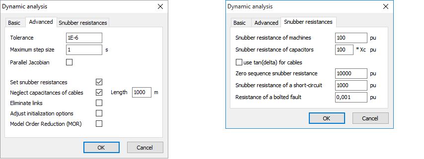
The tolerance and maximum step size of the numerical solver can be specified on tab Advanced. There it is also possible to specify values of the snubber resistances and neglect cable capacitances during dynamic analysis.

Tolerance
This is the coefficient that is used for weighting of the vector of local errors of system of differential equations. The value set by default is 1E-6. The decrease of tolerances leads to more accurate numeric solution, but, on the other hand, this slows the computation significantly. The increase of tolerances results in faster solution, but can lead to numeric instability.
Maximum time step
This parameter gives the limit of the values of time steps that are used inside the numeric solver. The time step inside the solver is automatically changed, based on the value of local errors. Therefore, in most situations the explicit change of maximum and minimum time steps is not necessary.
Parallel Jacobian
This calculation option switches on and off the use of multiple processor cores. The use of all processor cores can speed up the calculation significantly in case of large networks. For small network this option is not necessary and can even lead to somewhat slower solution in some situations.
Neglect capacitances of cables
This option specifies whether the shunt capacitances of cables have to be neglected. Neglecting cable capacitances (in situations when they are not of importance) increases the computation significantly. This is especially important in case of short cables. Therefore it is possible to set the minimal length of cable with shunt capacitances. Cables having length longer or equal to the given length are modelled with shunt capacitances. For shorter cables there are no capacitances present in the model.
Eliminate links
Links are modelled in Vision as small resistances. The magnitude of this resistance is to be set via Vision Options (F11): Options | Calculation | General. These rather small resistances can cause bad numerical effects during dynamic simulation. If there are many links present in the network, the calculation may become significantly slower. Therefore, it is possible to eliminate links during dynamic simulation. In this case two nodes connected by a link are considered as a single node. The disadvantage of this is that the currents through links cannot be plotted anymore.
Set snubber resistances
Here the values of different snubber resistances that are used internally, can be adjusted. After checking this option tab Snubber resistances will appear.
The snubber resistances that can be modified are as follows:
•Snubber resistance of machines: internally the resistor is set at each terminal of each machine (due to the reasons related with numerical solution of differential equations). This resistance is specified in p.u. based on the nominal data of the machine. The default value of 100 p.u. means that the error in the calculation for 1 p.u. stator current will be in order of 1%).
•Snubber resistance of capacitors: there are no pure capacitances present in the module for dynamic analysis. The large resistance is connected internally to each capacitor. This prevents problems with numerical stability. The value of the resistance is given relatively to the reactance of the capacitor. The default value of 100 means that one hundred times larger resistor is set on each capacitor.
•Zero sequence snubber resistance is used to build-up the voltage in ungrounded parts of a network. P.u. value is based on global p.u. system (defined by nominal voltage of a bus and Sbase in general options of Vision).
•Snubber resistance of a short circuit is related with the internal model of a short circuit in DQ0 reference frame. P.u. value is based on global p.u. system.
•Resistance of a bolted fault: if the short circuit has zero resistance, then the small value of resistance is actually used. P.u. value is based on global p.u. system.
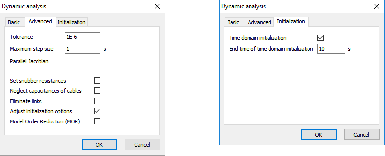
Initialization procedure
The initialization of the dynamic model in Vision is based on the loadflow results. The initial states are computed for specific operating point from the loadflow results using initialization procedures. Depending on the network and used elements, the operating point of the loadflow model and that of the dynamic model might slightly deviate from each other. This deviation is directly visible during time domain simulation since it does not begin in steady-state anymore (some transients in the begin of the simulation are to be observed, even if no dynamic case is executed). In case the network is stable (this can be easily checked by means of eigenvalue analysis), it can be chosen to determine the correct operating (steady-state) point by means of time domain simulation. During start of a dynamic analysis a pre-dynamic simulation can be executed, and the states at the end time (which is set by the user) can be used in order to initialize the system for the actual simulation. The initialization end time is dependent on the deviation of the initial operating point and the damping of the system. This time is set by default to 10 seconds.
