Calculation of short-circuit currents in accordance with the international standard IEC 60909 is described in the following reports:
IEC 60909-0
|
International standard Short-circuit currents in three-phase a.c. systems Part 0: Calculation of currents Second edition: 2016-01 |
IEC TR2 60909-1 |
Technical report Part 1: Factors for the calculation of short-circuit currents in three-phase a.c. systems according to IEC 60909-0 Second edition: 2002-07 |
IEC TR 60909-2 |
Technical report Part 2: Data of electrical equipment for short-circuit current calculations Second edition: 2008-11 |
IEC 60909-3 |
Technical report Part 3: Currents during two separate simultaneous line-to-earth short circuit currents and partial short-circuit currents flowing through earth Third edition: 2009-03 |
IEC TR2 60909-4 |
Technical report Part 4: Examples for the calculation of short-circuit currents Second edition: 2000-07 |
Changes compared to IEC 909
The standard IEC 60909 is a modernization of the old standard from 1988. The new standard has been in effect since 2001. The recent edition of IEC 60909 standard from 2016 introduces the method to deal with converter-connected generators. For the time being, both short-circuit methods will coexist in Vision. The most important changes are briefly explained below.
Correction factor c (clause 5.3.1)
In the old standard 909 the correction factor cmax was equal to 1.00 for 400V low-voltage systems with a tolerance of +6% and equal 1.05 for other low-voltage systems with a tolerance of +10%. This is now adjustable for low-voltage grids when calculating the maximum Ik". The choice consists of cmax = 1.05 for networks with a voltage tolerance of +6% and cmax = 1.10 for networks with a voltage tolerance of +10%. The correction factor is equalized to 0.95 for medium and high voltage systems there is no change.
Current conductor temperature (clause 7.1.2)
The starting point for the short-circuit calculations is always the worst-case scenario. This means that for the calculation of the largest short-circuit current the smallest conductor resistance is used. The standard assumes a conductor temperature of 20ºC.
For calculating the smallest short-circuit current the largest conductor resistance is used, which occurs at the conductor end temperature.
The final temperature depends on the cable type and is included in the cable type file.
Impedance mains supply (clause 6.2)
In the old IEC 909, the R/X ratio is a given, both in the normal and the zero-sequence system. The ratio Ik"3/Ik"1 (the quotient of the three-phase and one-phase short-circuit current) is a measure of the zero-sequence impedance Z0 of the power supply.
In the norm the R/X ratio is not mandatory and is available as an input.
If the ratio is unknown, the standard indicates that the impedance can be regarded as purely reactive in high-voltage networks (Un> 35kV). In other cases, a distribution of 0.0995 resistive and 0.995 reactive can be assumed, so that the R/X ratio is equal to 0.1.
Correction factor net transformers (clause 6.3.3)
A new factor has been introduced for correcting the impedances of transformers. The introduction of the correction factors for transformers has the largest influence on the short-circuit calculation of all changes in the standard. The correction factor is a function of the relative short-circuit voltage. In particular for transformers with a high Uk the correction factor on the impedance becomes small, so that the initial short-circuit current according to the new standard becomes greater than when the old standard is applied.
Incidentally, this factor is not applied to step-up transformers.
Power Station Unit (clause 6.7)
A combination of a synchronous generator and a step-up transformer is seen as an excitation unit. Generator and transformer are then jointly modelled. Vision recognizes this if the transformer is a "step-up" transformer. See: Power Station Unit.
Asynchronous engines (clause 6.10 / 6.11)
In the old standard IEC 909 the ratio of R/X was prescribed. The new standard may include a known ratio. If that ratio is not known, the old prescribed values can be used.
Motors that are controlled through static converters can provide a short-circuit contribution and these must also be modelled. They contribute to the symmetrical short-circuit current Ik" and to the peak short-circuit current Ip. In the calculation for the contribution, an asynchronous motor with drive is modelled in the same way as an asynchronous motor. However, they do not contribute to the symmetrical breaking current Ib and to the steady-state short-circuit current Ik.
Converter-connected generators (clause 6.9)
Converter-connected generators are introduced in the latest edition of IEC 60909 standard. They are treated as constant current sources in positive sequence circuit. Short-circuit contribution of these generators is mostly limited to the nominal current (only during maximal short-circuit current calculation). During minimal short-circuit current calculation the contribution is neglected. The short-circuit currents of converter-connected generators have to be added using superposition principle to the total subtransient short-circuit current (see, for instance, equation (34) for the three-phase short-circuit), the peak current (equation (61)), the breaking currents (equation (77)) and the steady-state short-circuit current (clause 11.2).
Symbols
The following symbols are used in this section:
Fault |
fault type: symmetrical, phase-phase, phase-phase-earth or phase-earth |
Situation |
indicates whether maximum or minimum short-circuit currents are calculated |
Sk" |
sub-transient short-circuit power (Ik" * √3 * Unom) |
Ik" |
sub-transient short-circuit current |
Ik"a,b,c |
sub-transient short-circuit current per phase |
Ip |
peak short-circuit current (kappa * √2 * Ik") |
Ib |
breaking current |
Ik"e |
short-circuit current to ground (with fault types phase-phase-earth or phase-earth) |
Ir |
rated current |
Zi |
network impedance at the node |
R/X |
R/X ratio of the network impedance at the node |
Ik"1 |
maximum branch currents occurring with a fault close to the "from" node |
Ik"1a,b,c |
maximum branch currents occurring per phase with a fault close to the "from" node |
Ik"2 |
maximum branch currents occurring with a fault close to the "to" node |
Ik"2a,b,c |
maximum branch currents occurring per phase with a fault close to the "to" node |
Ik,1s |
admissible short-circuit current for 1 second (lines) |
Ik,2s |
admissible short-circuit current (LV side) for 2 seconds (transformers) |
tmax |
admissible short-circuit time |
Imax |
maximum through going short-circuit current (with transformers only) |
I'' |
Sub-transient branch or element current that contributes to the short-circuit current |
I |
Stationary branch or element current that contributes to the short-circuit current |
m |
rated active power of motors (MW) per pair of poles |
Short-circuit calculations using Vision in accordance with IEC 60909
The method applied by IEC 60909 is based on superposition. The network is represented passively, whereby active elements such as generators and motors are replaced with impedances to earth. A negative voltage source is applied at the fault location. The currents which arise as a result of the voltage source are the fault currents, while the total current which is supplied by the voltage source is the short-circuit current.
The figure below shows a simple Vision network which consists of three nodes. Node K1 is connected to the source, and node K3 contains a load, a generator and a motor. A symmetrical short circuit is assumed at node K2.

Network in Vision with short circuit at node K2
In accordance with IEC 60909, the network can be replaced for the determination of the short-circuit current with the network as shown in the Figure below, whereby loads and shunts are always disregarded. The capacities of lines of the normal (Z1) and inverse system (Z2) are also not taken into consideration.
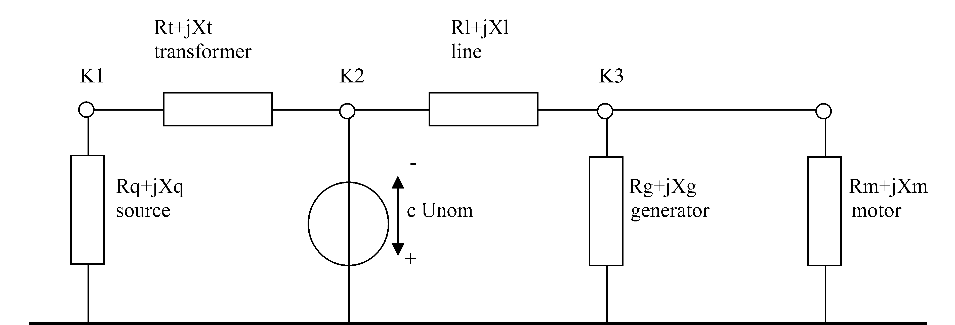
Network in accordance with IEC 60909
All branches and active elements are replaced with impedances comprising R + jX. The method used to determine R and X is described in the component descriptions. A voltage source is applied to node K2 (the fault location), with the following voltage:
Ufault location = -c * Unom
The voltage factor c is dependent on the voltage level, and on the choice as to whether minimum short-circuit currents (cmin) or maximum short-circuit currents (cmax) are to be calculated. The values for c are given in the table below.
Unom |
|
cmax |
cmin |
LV |
Tolerance +6% Tolerance +10% |
1.05 1.10 |
0.95 0.95 |
MV |
1 kV < Unom <= 35 kV |
1.10 |
1.00 |
HV |
35 kV <= Unom <= 230 kV 1) |
1.10 |
1.00 |
1) This last limit is not present in Vision. Networks with Unom higher than 230 kV are treated in the same way as other HV networks (see also VDE 0102).
IEC 60909 distinguishes between maximum occurring short-circuit currents (Ik"max) and minimum occurring short-circuit currents (Ik"min) at a fault location. Both calculations can be carried out using Vision.
Calculation of conductor resistance
The conductor resistance is specified for a reference temperature TR. The resistance for the actual temperature Tact will be calculated using the correction factor: (1+0.004(Tact-20)) / (1+0.004(TR-20)).
Maximum short-circuit current calculation Ik"max
In calculating maximum short-circuit currents in a network, a c-factor >= 1 is used. The following are also assumed for the calculation:
•conductors resistance at a temperature of 20 degrees C
•maximum usage of generators
•maximum usage of transformers
•maximum short-circuit power of source
•supply from asynchronous machines (generators and motors)
Minimum short-circuit current calculation Ik"min
In calculating minimum short-circuit currents in a network, a c-factor <= 1 is used. The following are also assumed for the calculation:
•conductors resistance at a higher temperature (at the end of the short-circuit duration)
•minimum usage of generators
•minimum usage of transformers
•minimum short-circuit power of source. The minimum short-circuit power of the source must be at least 10 % less than the maximum short-circuit power necessary to determine maximum short-circuit currents.
The influence of asynchronous machines (generators and motors) and synchronous motors is not taken into consideration in the calculation of minimum short-circuit currents.
Short-circuit calculations on nodes
The Figure below shows the history of a short-circuit current, whereby the relationship is shown between the peak short-circuit current Ip and the sub-transient short-circuit current Ik". Ik" changes into the steady-state short-circuit current Ik.
For faults a considerable distance away from generators, in many cases it can be assumed that Ik is equal to Ik".
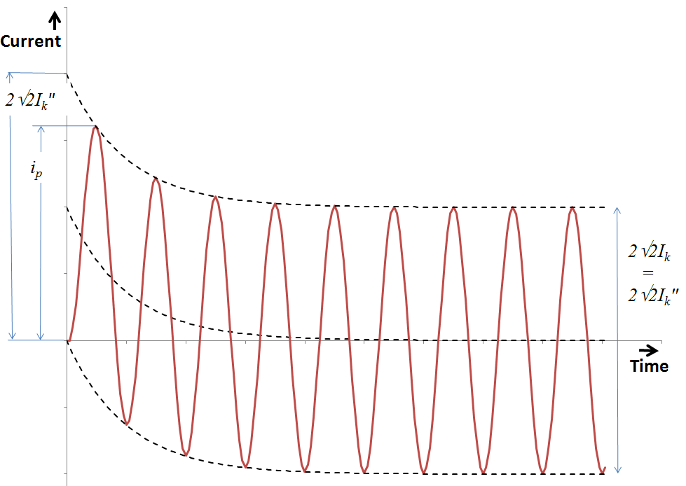
Ik = f(t)
With faults near to generators, Ik is always less than Ik".
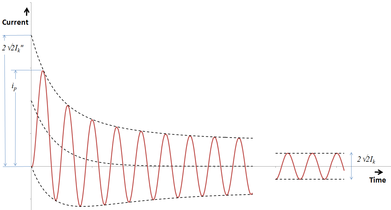
In a near-to-generator short circuit, the short-circuit current behaves generally as shown in the figure above. In some special cases it could happen that the decaying short-circuit current reaches zero for the first time, some periods after the short circuit took place. This is possible if the d.c. time constant of a synchronous machine is larger than the subtransient time constant. This phenomenon is not dealt with in detail by the IEC 60909 standard and also not in the IEC module of Vision.
Peak short-circuit current
The peak short-circuit current Ip is determined from Ik" in accordance with the following:
Ip = κ ⋅ √2 ⋅ Ik"
Three methods are given in IEC 60909 for determining the factor kappa (IEC 60909-0, clause 4.3.1.2). Differences between the methods relate to the required accuracy and to the choice of whether to perform calculations on radial or meshed networks. A meshed network is understood to mean the following in accordance with the standard: any network in which the short-circuit current can be supplied from different directions. Thus, for example, a radially-operated 10 kV network incorporating a self-generator or asynchronous machines is a meshed network.
"Method C" given in the standard is used in Vision. This method can be used for both radial and meshed networks. It determines the R/X ratio using an impedance Zc = Rc + jXc determined at fc = 0.4 * 50 Hz (or fc = 0.4 * 60 Hz) in accordance with the following:
R/X = (Rc / Xc) ⋅ (fc / f)
where:
| R/X | the R/X ratio at the fault location |
| Rc | the real part of the network impedance Zc at the fault location at 20 Hz (or 24 Hz) |
| Xc | the imaginary part of the network impedance Zc at the fault location at 20 Hz (or 24 Hz) |
| fc | frequency at which Zc is determined: 20 Hz (or 24 Hz) |
| f | network frequency: 50 Hz (or 60 Hz) |
The following is then determined using the formula:
κ = 1.02 + 0.98 exp(-3 R/X)
The peak current is calculated only at the maximum short-circuit current.
Breaking current
Far-from-generator short-circuit
For far-from-generator short-circuits, the short-circuit breaking currents are equal to the initial short-circuit currents. Therefore these breaking currents will not be calculated explicitly.
Near-to-generator short-circuit
The implemented method for calculation of the breaking current follows the method for a three-phase short-circuit in meshed networks, for near-to-generator short-circuits.
The breaking current is calculated at a symmetrical fault on one selected node for 4 steps in time. Hereby the decrease of short-circuit current for every machine is calculated with the following equation.
![]()
Where:
ΔU"G = jXd" Ik"G for synchronous generators and synchronous motors
ΔU"M = jXd" Ik"M for asynchronous motors
The first part of the equation is valid for all synchronous generators and motors. The second part of the equation is only valid for asynchronous motors. For asynchronous generators no decrease is calculated.
The factors q and mu are calculated for the four steps in time with the following equations.
q = 1.03 + 0.12 ln(m) while t = 0.02 s
q = 0.79 + 0.12 ln(m) while t = 0.05 s
q = 0.57 + 0.12 ln(m) while t = 0.10 s
q = 0.26 + 0.10 ln(m) while t >= 0.25 s
μ = 0.84 + 0.26 exp(-0.26 I"k / Ir ) while t = 0.02 s
μ = 0.71 + 0.51 exp(-0.30 I"k / Ir ) while t = 0.05 s
μ = 0.62 + 0.72 exp(-0.32 I"k / Ir ) while t = 0.10 s
μ = 0.56 + 0.94 exp(-0.38 I"k / Ir ) while t >= 0.25 s
The breaking current is calculated only for maximum short-circuit currents.
Short-circuit calculations on branches
In short-circuit calculations on branches, the total short-circuit current at the fault location is not shown in Vision, but the greatest current which can occur in a cable, line, reactance coil or transformer. This is illustrated for a line in the Figure shown below. The greatest currents in a line arise with faults close to the "from" node or close to the "to" node. With a fault close to the "from" node K1, the currents I1 and I2 occur in the line, giving the short-circuit current Ik" when added together. As this current is not relevant for the sizing of the line, only the greatest of the currents I1 and I2 is represented with Ik"1 in Vision. The same applies to a fault close to the "to" node K2, and the greatest of currents I3 and I4 is indicated with Ik"2.
The indices 1 and 2 in Ik" distinguish between the "from" and "to" nodes.
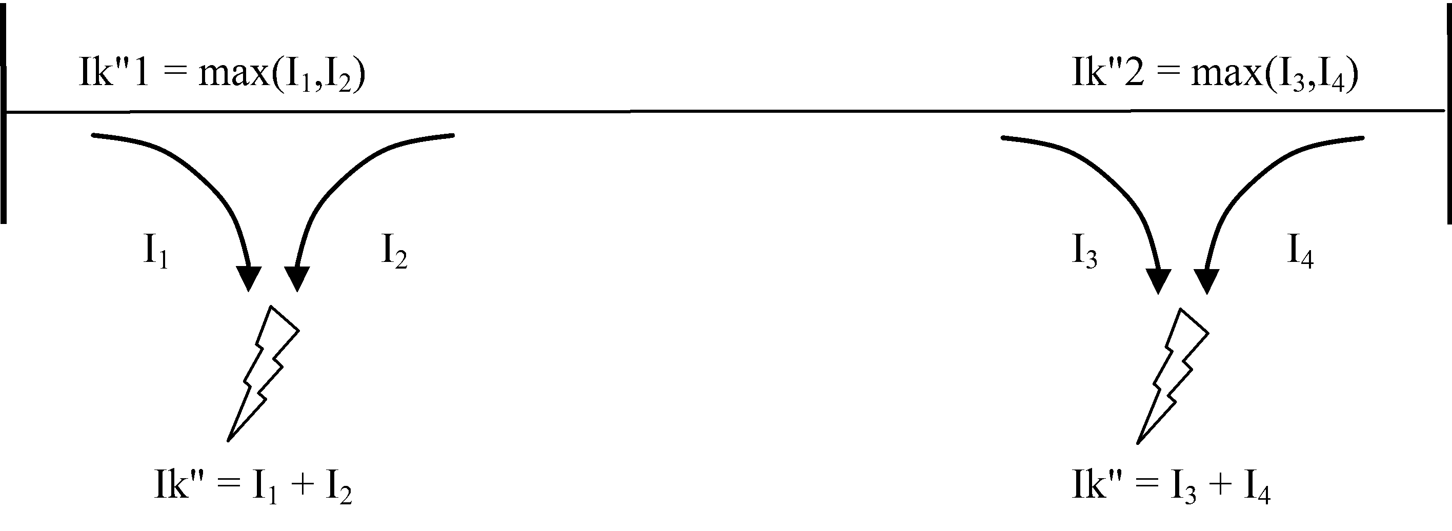
Determination of Ik"1 and Ik"2 for lines
For transformers, the same approach applies as for lines. Once again here, the currents Ik"1 and Ik"2, which may occur in the branch close to the "from" and "to" node respectively, are calculated. These values are significant with regard to transformers, as they are the maximum currents which can occur in the connecting cables of the transformer.
In addition, the current Imax is also calculated. This is the maximum of the currents I2 and I3 (LV side) and thus the maximum continuous short-circuit current which can occur in the transformer. The following Figure shows how Ik"1, Ik"2 and Imax are determined for transformers.
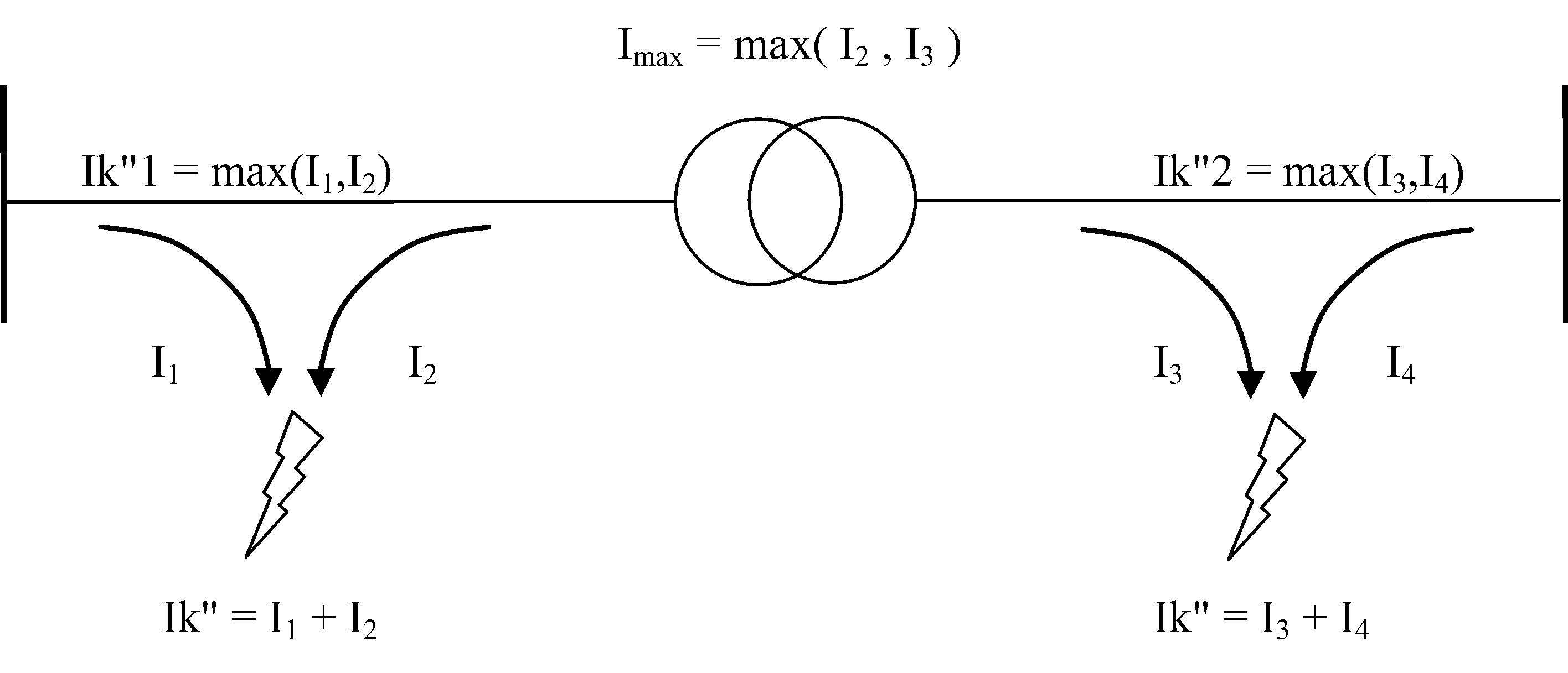
Determination of Ik"1, Ik"2 and Imax for transformers
Imax is determined in the same way for three-winding transformers.
Admissible short-circuit time
The maximum admissible short-circuit time tmax is calculated using the stated Ik,1s or Ik,2s for all branches for which an IEC 60909 calculation is carried out.
For lines:
tmax = 1 (second) ⋅ (Ik,1s / Ik")²
For transformers and reactance coils:
tmax = 2 (seconds) ⋅ (Ik,2s / Imax)²
where:
tmax |
Maximum admissible short-circuit time |
Ik,1s |
Admissible short-circuit current for 1 second (lines and cables) |
Ik,2s |
Admissible short-circuit current (LV side) for 2 seconds (transformers and reactance coils) |
Ik" |
Maximum occurring short-circuit current in the branch (max(Ik"1, Ik"2)) |
Imax |
Maximum continuous short-circuit current (transformers) |
Asymmetrical short-circuit calculations
In addition to symmetrical faults (PPP), the following asymmetrical faults can also be calculated: phase - earth (PE), phase - phase (PP) and phase - phase - earth (PPE).
The symmetrical components method is used for the calculation. This is a methodology for enabling easier calculation of asymmetrical loads in a three-phase system by means of a transformation. Other names for this method include the 0-1-2-components method or the Fortescue transformation.
The aim of this transformation is to obtain three uncoupled single-phase systems from a coupled three-phase system. The three systems are:
•the normal system (index 1); this is a symmetrical three-phase system with normal phase sequence (120° phase shift)
•the inverse system (index 2); this is a symmetrical three-phase system with inverse phase sequence (-120° phase shift)
•the zero sequence system (index 0); in this case, the currents and voltages are the same size and display the same phase relation.
The impedance of the normal system (Z1) can be measured with a supply consisting of a normal-cycle three-phase system. This impedance corresponds to the normal operational impedance.
The inverse impedance (Z2) can be measured with a supply consisting of an inverse-cycle three-phase system. For all static network components, this corresponds to the normal impedance. For asynchronous machines and two-pole synchronous machines, however, Z2 is approximately equal to Z1. As there is no specification in IEC 60909 with regard to inverse impedance, Z2 = Z1 is applied in Vision, including all correction factors.
For the calculation of earth to ground faults the following rules apply:
•The zero sequence resistance may not be smaller than the normal operational resistance.
•The zero sequence reactance may not be zero.
For transformers:
•The zero sequence impedance may not be zero.
The zero sequence impedance (Z0) can be measured with a supply consisting of a zero sequence system. This is difficult to ascertain, particularly for cable connections.
The symmetrical components method is used to calculate all short-circuit and phase currents in Vision.
Provided that Z2 = Z1 and arg(Z1) is approximately equal to arg(Z0), the following apply:
•in the case of the greatest short-circuit currents, the single-phase short-circuit current (PE) is greater than the symmetrical short-circuit current (PPP), if Z1 / Z0 > 1
•in the case of the smallest short-circuit currents, the single-phase short-circuit current (PE) is smaller than the two-phase short-circuit current without earth contact (PP), if Z1 / Z0 < 0.683.
See also: