The network model in the module is suitable for the analysis of electromagnetic transients with duration from hundreds milliseconds till several seconds. The typical examples of these are short-circuits and voltage dips. Electromechanic transients such as the start of a motor or rotor angle / rotor speed oscillations of electrical machines (transient stability) after short circuit can also be studied with this model. Fast electromagnetic transients, for instance, the behavior of the network after a lightning strike or development of the arc after a short circuit, currently cannot be modeled.
In the electromagnetic approach all objects are modeled with differential equations. Each coil/capacitor is modeled by a differential equation. The simulation with this model is very accurate, but costs relatively a lot time. Therefore, the module is more suitable for the analysis of small to medium size networks.
In order to increase the simulation speed the transformation to the synchronously rotating DQ0 reference frame can be used. The biggest advantage of DQ0 reference frame is that the voltages and currents during steady-state situation are constant, while they vary sinusoidal in the usual ABC reference. Together with the use of variable time step solver for the numerical solution of differential equations this results in faster computations than in traditional packages for simulation of electromagnetic transients.
The types of objects modeled for dynamic analysis are as follows:
•cables and cable/line equivalents;
•two- and three-winding transformers;
•zigzag grounding transformers;
•grids (external networks);
•loads;
•shunt capacitors;
•shunt and series reactors;
•induction generators and motors;
•synchronous motors;
•synchronous generators including:
oexcitation systems;
opower system stabilizer;
oreactive power and power factor controls;
oturbine and governing system.
All models, except that of synchronous and induction machines, use no extra parameters with respect to the parameters of static calculations. For the Y-connected elements it can be chosen on tab Neutral whether the neutral point is isolated, grounded or grounded via impedance.
Cable and cable/line equivalent
All cables and cable/line equivalents are represented by one or multiple π-section models or T-section models. It is possible to neglect the shunt capacitances of cables. This can be done collectively via the calculation options of Dynamic Analysis on tab Advanced or by selecting Neglect cable capacitances in the tab Dynamic of the cable options. Neglecting the shunt capacitances (in situations when they are of little influence, for instance, for very short cables) results in a great speedup of the simulation.
Transformer
The transformer is modeled by a set of three mutually coupled coils. Parameters of transformer are determined from the short circuit and no load transformer tests. For a correct dynamic model the no load transformer current is of big importance. From this current the value of mutual inductive coupling between the coils is determined. In case the no load current is unknown, it can be set to a value between 1% and 2% of the nominal current of the transformer. This would guarantee that the mutual couplings in the transformer model are large enough.
Zigzag transformer
The zigzag transformer is modeled by a zero-sequence resistance R0 and reactance X0. In case the neutral point of the grounding transformer is grounded via impedance Re+jXe, it can be specified on tab Neutral. The total zero-sequence resistance and reactance of the zigzag transformer is then determined as: R0+3*Ra en X0+3*Xa.
Grid
The grid (external network) is modeled by the three phase voltage source behind the resistor and inductor. There exists the possibility to dynamically define the voltage of the source in each phase (see Case and events). In such manner the voltage dip in the network can be simulated.
Load
The load is represented by constant impedance model. For inductive loads the series connection of resistors and inductors is used. For capacitive load the parallel connection of resistors and capacitors is used. Loads are Y-connected and balanced.
Capacitor
The capacitor is represented by capacitances in three phases. Only Y-connection of the phases is currently supported.
Coil
The coil is represented by inductances in three phases. Only Y-connection of phases is supported.
Synchronous generator and motor
The synchronous machine is represented by the detailed electromagnetic model. For description, see for instance the book of Kundur “Power System Stability and Control”.
Machines with salient pole rotor are modeled by 8 differential equations:
•3 differential equations for stator fluxes
•1 differential equations for the field winding
•2 differential equations for damper windings (1d, 1q)
•1 differential equations for the rotor speed
•1 differential equations for the rotor angle.
Machines with round rotor are modeled by 9 differential equations:
•3 differential equations for stator fluxes
•1 differential equations for the field winding
•3 differential equations for damper windings (1d, 1q, 2q)
•1 differential equations for the rotor speed
•1 differential equations for the rotor angle.
Parameters of the model are determined from the synchronous, transient and subtransient reactances and time constants. For dynamic modelling of synchronous machine are extra parameters necessary. These parameters are located on the tab Dynamic of the input window.
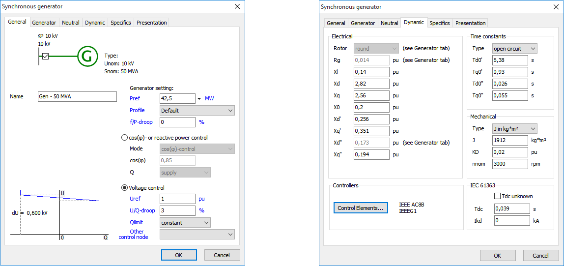
Some parameters are already filled-in in other tabs, for instance, the rotor type, the stator resistance Rg and the subtransient reactance on the d-axis Xd’’. Other parameters that still have to be filled-in are:
Parameter |
Unit |
Description |
Xl |
p.u. |
leakage reactance |
Xd |
p.u. |
synchronous reactance, d-axis |
Xq |
p.u. |
synchronous reactance, q-axis |
X0 |
p.u. |
zero sequence reactance |
Xd' |
p.u. |
transient reactance, d-axis |
Xq' |
p.u. |
transient reactance, q-axis (n.a. for salient pole rotor machine) |
Xd'' |
p.u. |
subtransient reactance, d-axis |
Xq’’ |
p.u. |
subtransient reactance, q-axis |
Td0’ or Td’ |
s |
open- or short-circuit transient time constant, d-axis |
Tq0’ or Tq’ |
s |
open- or short-circuit transient time constant, q-axis (n.a. for salient pole rotor machine) |
Td0’’ or Td’’ |
s |
open- or short-circuit subtransient time constant, d-axis |
Tq0’’ or Tq’’ |
s |
open- or short-circuit subtransient time constant, q-axis |
H or J |
s or kg∙m2 |
inertia, rotor and turbine together (H in s based on Snom) |
KD |
p.u. |
damping coefficient of the rotor speed (in case it is not known: use zero) |
nnom |
r.p.m. |
nominal speed |
All resistances and reactances are in p.u. based on the nominal data of the machine.
Synchronous generator control elements
In order to model the influence of synchronous generator controls during dynamic analysis, the control elements and respective parameters have to be specified. This can be done by clicking Control Elements… button on tab Dynamic in the parameters of the synchronous generator.
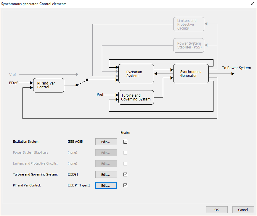
This form gives an overview of the chosen control strategy and respective control elements. Using Edit… button it is possible to choose the controller type (this will be described in more detail below) and specify the parameters of controller. By checking and unchecking Enable checkboxes a control system can be switched on and off. In case a control system is switched off, it is represented by a constant input, the value for which is determined during the initialization (from the results of the loadflow calculation). ‘Power System Stabilizer’ and ‘Over- and Underexcitation Limiters’ are currently not modeled.
Excitation system
The basic function of an excitation system is to provide a controlled DC current to the field winding of the synchronous generator. Due to variation of this current the magnetic field of the rotor changes and the voltage induced in the stator windings changes as well. On the form shown below it can be chosen between 20 standard IEEE models (IEEE Std. 421.5-2005).
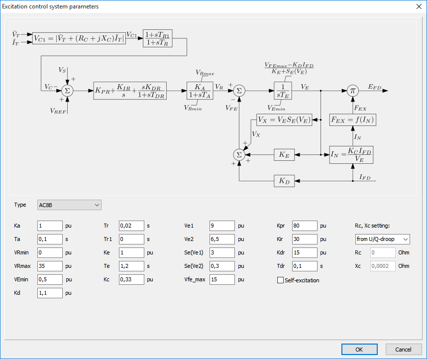
The parameters filled-in by default can be used just as an example. These are neither typical nor representative. For a detailed description of the models and the detailed example, please see:
http://www.phasetophase.nl/pdf/SynchronousMachineExcitationSystems.pdf
Turbine and governing system
Besides the excitation of the field winding the behavior of a synchronous generator is influenced by a prime mover and its control. Correct modelling of turbine and governing system is especially important for the transient stability studies, where analysis of large disturbances is of concern. Five models proposed by IEEE (PES-TR1) are currently implemented in Vision (see form below).
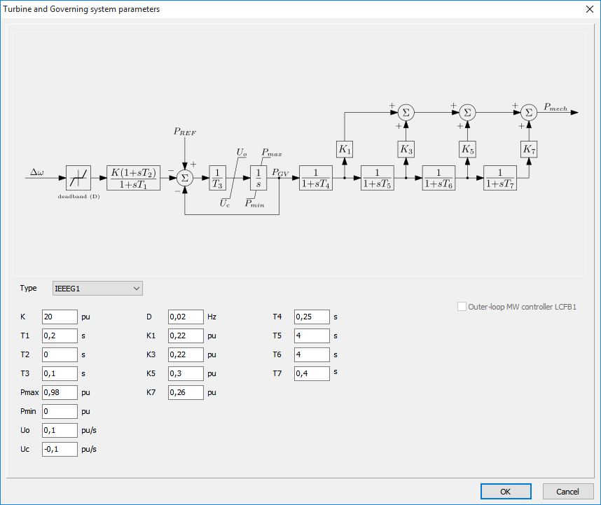
The parameters filled-in by default can be used just as an example. These are neither typical nor representative. For a detailed description of the models and the detailed example, please see:
http://www.phasetophase.nl/pdf/SynchronousMachineTurbineGoverningSystems.pdf
Power System Stabilizer
The Power System Stabilizer (PSS) is used to enhance damping of power system oscillations through excitation control.A logical signal to be used as an input to the PSS is the speed deviation Δω, other inputs could be the frequency and power. On the form shown below the IEEE PSS1A model is shown together with the input parameters (IEEE Std. 421.5-2005).
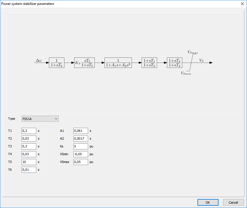
The parameters filled-in by default can be used just as an example. These are neither typical nor representative. For a detailed description of the models and the detailed example, please see:
http://www.phasetophase.nl/pdf/SynchronousMachineExcitationSystems.pdf
Reactive power and power factor control
Excitation systems are sometimes equipped with a reactive power or power factor control. This control is implemented as a slow outer loop controller for the excitation and automatic voltage regulator. The reference voltage VREF is controlled by a PI controller that minimizes the difference between the reference signal and the measured reactive power or power factor.
Reactive power/power factor control is used typically for the industrial applications. For such applications the generator is usually connected to the plant distribution bus. The voltage on the terminals of the generator has to follow the value determined by the external network and voltage control of the generator is not desirable in this case. In Vision PF controller Type II and var controller Type II models from IEEE standard (Std. 421.5-2005) are implemented. The controller type and its parameters can be specified using form shown below.
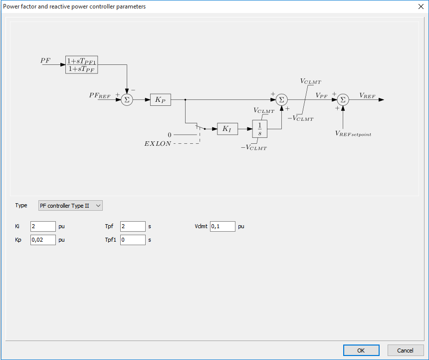
The parameters filled-in by default can be used just as an example. These are neither typical nor representative. For a detailed description of the models and the detailed example, please see: http://www.phasetophase.nl/pdf/SynchronousMachineExcitationSystems.pdf
Induction generator and motor
The induction machine is represented by the detailed electromagnetic model. For detailed description of the model see, for instance, the book of Krause “Analysis of Electric Machinery and Drive Systems”. It is possible to choose between single cage and double cage model. Single cage model is the most widely known model, but it is in general not precise enough to model well both the startup and the short circuit behavior of the machine. The double cage model solves this problem. Therefore, it is advised to use by default the double cage model.
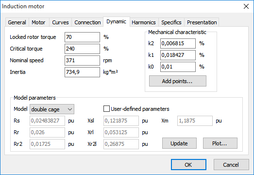
Extra parameters of the induction machine are:
•Locked rotor torque, in percent of the nominal torque
•Critical torque, in procent of nominal torque
•Nominal speed, r.p.m.
•Inertia, kg*m² (rotor and drive mechanism summed up)
•k2, k1, k0 are the coefficients of the quadratic approximation of the mechanical characteristic of the driven mechanism: Tm = k2∙n² + k1∙n + k0, where Tm is the mechanical torque in percent of nominal and n is the speed in percent of nominal speed. It is possible to use linear approximation (k2 = 0) or a constant mechanical torque (k2 and k1 = 0).
The easiest way to enter the mechanical characteristic of the machine is via addition of the measured points (button Add points…). The following form appears after click on the button:
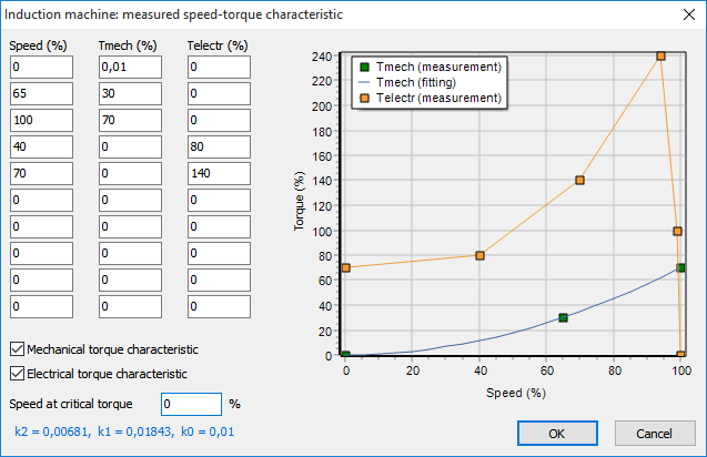
The measured points of the mechanical torque-speed characteristic and/or these of the electrical torque-speed characteristic can be entered here. The points of the mechanical torque characteristic are used for the automatic computation of the best coefficients k2, k1 and k0. If you click on OK button, the values of the coefficients are automatically filled-in in the respective fields. The added points of the electrical torque characteristic (if they are known) are used for the better estimation of model parameters. If the speed at critical torque is known, it can be also added. In case it is unknown, you can set zero as a value (internally it will be determined automatically).
Model parameters are used for automatic solution of the following optimization problem: find model parameters that approximate the known points of electrical torque-speed and stator current-speed characteristics as good as possible. If no extra points are available, then only locked rotor current, lock rotor torque, critical torque and the nominal data of the machine are used for the automatic estimation of model parameters. But if more points are specified, the model approximates the reality better.
It is also possible to specify own model parameters by checking User-defined parameters.
Update button is used for automatic computation of model parameters via optimization. The automatic calculation is also applied in case if User-defined parameters is not checked and one or more parameters have changed (for instance, the locked rotor torque) and you click on OK button.
The button Plot… shows torque-speed and stator current-speed characteristics for the given model parameters.
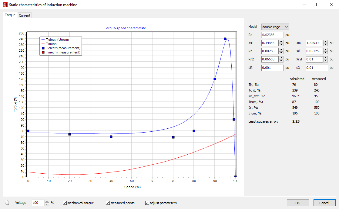
The characteristics are plotted normally at the nominal voltage. In case of deviating stator voltages it is also possible to adjust it using Voltage input field.
Checkbox measured points shows the points specified earlier via Add points…
Checkbox adjust parameters lets the user to visualize immediately the influence of model parameters adjustment on the characteristics. This adjustment takes place via direct changing of parameter value or via clicking arrows next to respective input field. In the last case the corresponding parameter is increased/decreased by the value specified in dR (for resistance) or dX (for reactance) input field. Deviations for important points are summed up in numerical form on the right hand side of the window. Calculated points come from the calculation of characteristics using model parameters. Measured points were specified by the user earlier by entering the induction machine nameplate data. Least squares error gives how close the calculated characteristics approximate the reality (the measured points). The smaller is this number, the better is approximation. If the parameters were changed and OK button is clicked, then the parameters will be automatically entered in the respective input fields of the main window of the induction machine.