The three-winding transformer is an object that has many embodiments. Thus, due to the combinations of circuits of the windings, many conventional and less common types are conceivable. This chapter deals with the input fields of the three winding transformer.
PARAMETERS
General
The windings of a three-winding transformer are automatically assigned by Vision to the nodes in the grid. The primary winding is always assigned to the node with the highest nominal voltage. The tertiary winding is always assigned to the node with the lowest nominal voltage. In the event that nodes have equal nominal voltages, the windings are assigned in order of user input of the nodes. Thus when 380/50/380 kV is entered and the nodes have this sequence, the primary and secondary windings are 380 kV and the tertiary winding is 50 kV.
Parameter |
Description |
Name |
Name of the transformer |
Tap |
Tap of the regulated and adjustable switch |
Three winding transformer
Parameter |
Default |
Unit |
Description |
Type |
|
|
Transformer type |
General |
|
|
|
Snom |
0 |
MVA |
Nominal apparent power |
Unom |
1) |
kV |
Nominal winding voltage |
Ik (2 s) |
0 |
kA |
Admissible short-circuit current for 2 seconds |
Connection |
2) |
D / Y / YN / Z / ZN |
Connection of the windings |
Clock |
2) |
|
Winding to winding configuration |
Impedances |
|
|
|
uk |
0 |
% |
Relative short-circuit voltage |
Pk |
0 |
kW |
Short-circuit loss |
at S |
|
MVA |
Uk and Pk reference MVA |
Z0 |
0 |
Ohm |
Zero sequence impedance (see explanation for circuit below) |
R0 |
0 |
Ohm |
Zero sequence resistance (see explanation for circuit below) |
Pnul |
0 |
kW |
No-load loss |
Inul |
0 |
A |
No-load current (at LV side) |
Tap |
|
|
|
Tap side |
w1 |
|
Location of the tap changer |
Tap size |
0 |
kV |
Tap size of the tap changer |
Tap min |
0 |
|
Tap with smallest number of windings |
Tap nom |
0 |
|
Tap with nominal transfer ratio |
Tap max |
0 |
|
Tap with greatest number of windings |
1) The default value of the nominal voltage is chosen equal to the nominal voltage of the node to which the winding is connected
2) The default connection and clock number is selected on the basis of the nominal voltage of the respective winding
Unom
With a new three winding transformer, the nominal voltage of the windings Unom,w1, Unom,w2 and Unom,w3 is determined based on the nominal voltage of the connected nodes.
Type
The type list contains all three winding transformers from the component type database for which Unom,w1, Unom,w2 and Unom,w3 are between 0.8*Unom and 1.2*Unom for all three of the nodes.
See also: Type
Clock
The clock number denotes the windings configuration to enable the calculation of phase voltages and phase currents during fault conditions.
at S
The transformer parameters will be calculated from uk and Pk, using the minimum value of the rated powers of the two related windings. However, if at S has been specified for the related parameters, this value will be used instead of the minimum rated power.
Tap min, nom and max
The indication of the tap position can be defined by the user by indicating the minimum, nominal and maximum tap position. Note that, for example, the minimum tap position can be defined as the tap position at the smallest number of windings and thus (depending on the tap side) can give the largest voltage ratio!
Z0 and R0
The starting point for the input of the zero sequence impedances is always a measurement. The measured values can be found in the measurement report of the installed three winding transformer. Depending on the type of connection, the zero sequence impedances are measurable and applicable. Sometimes a single measurement is sufficient (for example with a YNdd-transformer) but sometimes three measurements are required. Sometimes windings have to be shorted when performing the measurements (YN-windings). If a winding for the measurement is shorted, it may be that the value of two parallel-connected windings (for example a shorted YN and a D-winding) is measured.
With 98 of all 125 possible connections, the zero sequence impedance (Z0) and resistance (R0) must be entered according to the table below. This also applies to the values in the type file. A measurement can only be performed from a YN-winding or from a ZN-winding. Incidentally, a ZN-winding does not have a continuous zero sequence coupling with the other windings. For each transformer connection, it is indicated in the table below with the aid of a code whether windings are shorted for the measurements. If for a measurement a YN-winding needs to be shorted at the other side, it is indicated by an exclamation mark (for example: measuring winding 1 with winding 2 shorted: w1 -> w2!). A D-winding is by definition always shorted for zero sequence flows and this is not explicitly stated in the code. A measurement from a winding can also be carried out with the two other windings shorted (shorted YN or D). In the network model, these two windings are parallel for the zero sequence flows. This is indicated in the table by // (for example: measuring on winding 1 with winding 2 a shorted YN-winding and winding 3 a D winding: w1 -> w2! // w3).
If, for example, a YNYND-transformer is measured, there are four different ways to measure the zero sequence impedances:
1.measure winding 1, with winding 2 open; in that case, winding 1 and the transformation of winding 3 (triangular winding) are measured (indicated by: w1-> w3).
2.measuring winding 1, with winding 2 shorted; in that case, winding 1 and the transformation of winding 2 (shorted YN) are measured in parallel with winding 3 (triangle winding) (indicated by: w1-> w2! // w3).
3.measure winding 2, with winding 1 open; in that case, winding 2 and the transformation of winding 3 (triangular winding) are measured (indicated by: w 2 -> w 3).
4.measuring winding 2, with winding 1 shorted; in that case, winding 2 and the transformation of winding 1 (shorted YN) are measured in parallel with winding 3 (triangular winding) (indicated by: w2-> w1! // w3).
Only three of the four measurements are needed to derive the zero sequence network model parameters. In the example above, measurements 1, 2 and 3 have been implemented for the YNYND-transformer in the table below.
The table below lists all the measurements that are used to derive the model parameters. The indicated measurement results are entered in the transformer form for the zero sequence impedances.
Connection |
Z0_12 and R0_12 |
Z0_13 and R0_13 |
Z0_23 and R0_23 |
|---|---|---|---|
YN YN YN |
w1->w2! |
w1->w3! |
w2->w3! |
YN YN Y |
w1->w2! |
|
|
YN YN ZN |
w1->w2! |
|
w3 |
YN YN Z |
w1->w2! |
|
|
YN YN D |
w1->w2!//w3 |
w1->w3 |
w2->w3 |
YN Y YN |
|
w1->w3! |
|
YN Y Y |
w1 |
|
|
YN Y ZN |
|
|
w3 |
YN Y Z |
w1 |
|
|
YN Y D |
|
w1->w3 |
|
YN ZN YN |
|
w1->w3! |
w2 |
YN ZN Y |
|
w2 |
|
YN ZN ZN |
|
w2 |
w3 |
YN ZN Z |
|
w2 |
|
YN ZN D |
|
w1->w3 |
w2 |
YN Z YN |
|
w1->w3! |
|
YN Z Y |
w1 |
|
|
YN Z ZN |
|
|
w3 |
YN Z Z |
w1 |
|
|
YN Z D |
|
w1->w3 |
|
YN D YN |
w1->w2 |
w1->w3!//w2 |
w3->w2 |
YN D Y |
w1->w2 |
|
|
YN D ZN |
w1->w2 |
|
w3 |
YN D Z |
w1->w2 |
|
|
YN D D |
w1->w2//w3 |
|
|
Y YN YN |
|
|
w2->w3! |
Y YN Y |
|
w2 |
|
Y YN ZN |
|
|
w3 |
Y YN Z |
|
w2 |
|
Y YN D |
|
|
w2->w3 |
Y Y YN |
|
|
w3 |
Y Y ZN |
|
|
w3 |
Y ZN YN |
|
w2 |
|
Y ZN Y |
|
w2 |
|
Y ZN ZN |
|
w2 |
w3 |
Y ZN Z |
|
w2 |
|
Y ZN D |
|
w2 |
|
Y Z YN |
|
|
w3 |
Y Z ZN |
|
|
w3 |
Y D YN |
|
|
w3->w2 |
Y D ZN |
|
|
w3 |
ZN YN YN |
w1 |
|
w2->w3! |
ZN YN Y |
w1 |
|
|
ZN YN ZN |
w1 |
|
w3 |
ZN YN Z |
w1 |
|
|
ZN YN D |
w1 |
|
w2->w3 |
ZN Y YN |
w1 |
|
|
ZN Y Y |
w1 |
|
|
ZN Y ZN |
w1 |
|
w3 |
ZN Y Z |
w1 |
|
|
ZN Y D |
w1 |
|
|
ZN ZN YN |
w1 |
w2 |
|
ZN ZN Y |
w1 |
w2 |
|
ZN ZN ZN |
w1 |
w2 |
w3 |
ZN ZN Z |
w1 |
w2 |
|
ZN ZN D |
w1 |
w2 |
|
ZN Z YN |
w1 |
|
|
ZN Z Y |
w1 |
|
|
ZN Z ZN |
w1 |
|
w3 |
ZN Z Z |
w1 |
|
|
ZN Z D |
w1 |
|
|
ZN D YN |
w1 |
|
w3->w2 |
ZN D Y |
w1 |
|
|
ZN D ZN |
w1 |
|
w3 |
ZN D Z |
w1 |
|
|
ZN D D |
w1 |
|
|
Z YN YN |
|
|
w2->w3! |
Z YN Y |
|
w2 |
|
Z YN ZN |
|
|
w3 |
Z YN Z |
|
w2 |
|
Z YN D |
|
|
w2->w3 |
Z Y YN |
|
|
w3 |
Z Y ZN |
|
|
w3 |
Z ZN YN |
|
w2 |
|
Z ZN Y |
|
w2 |
|
Z ZN ZN |
|
w2 |
w3 |
Z ZN Z |
|
w2 |
|
Z ZN D |
|
w2 |
|
Z Z YN |
|
|
w3 |
Z Z ZN |
|
|
w3 |
Z D YN |
|
|
w3->w2 |
Z D ZN |
|
|
w3 |
D YN YN |
w2->w1 |
w3->w1 |
w2->w3!//w1 |
D YN Y |
w2->w1 |
|
|
D YN ZN |
w2->w1 |
|
w3 |
D YN Z |
w2->w1 |
|
|
D YN D |
w2->w1//w3 |
|
|
D Y YN |
|
w3->w1 |
|
D Y ZN |
|
|
w3 |
D ZN YN |
|
w3->w1 |
w2 |
D ZN Y |
|
w2 |
|
D ZN ZN |
|
w2 |
w3 |
D ZN Z |
|
w2 |
|
D ZN D |
|
w2 |
|
D Z YN |
|
w3-w1 |
|
D Z ZN |
|
|
w3 |
D D YN |
|
w3->w1//w2 |
|
D D ZN |
|
|
w3 |
Zero sequence impedance for YNyy and YNyz three-windings transformer
In the case of a transformer consisting of one earthed star winding and two non-earthed windings in star or zigzag, the zero sequence impedance of the earthed winding is not neglected. As a result, in networks where these transformers are modelled, a value greater than zero must be entered for the zero sequence impedance of the earthed star winding. By default, the value is always zero, but the value for the zero sequence impedance of a transformer is a factor times the normal impedance. The factor depends on the construction of the core of the transformer. See the table below.
Core construction |
factor |
Three limps |
3 ... 10 |
Five limps |
10 ... 100 |
Three times one phase |
10 ... 100 |
Connection
Parameter |
Default |
Unit |
Description |
Neutral point |
own |
|
Earthing of the neutral point with a YN-winding |
Re |
0 |
Ohm |
Earthing resistance with earthed star point |
Xe |
0 |
Ohm |
Earthing reactance with earthed star point |
Snom' |
0 |
MVA |
Maximum apparent power; may differ from Snom |
Phase shift w1-w2 |
0 |
degrees |
Additional phase shift from winding 1 to 2 (between -15 .. +15 degrees) |
Phase shift w1-w3 |
0 |
degrees |
Additional phase shift from winding 1 to 3 (between -15 .. +15 degrees) |
Lmax (normal) |
0 |
% |
Alternative maximum load rating in normal situation; only if different from options |
Lmax (failure) |
0 |
% |
Alternative maximum load rating in failure situation; only if different from options |
Snom'
The variable Snom' has been introduced for a uniform overload indication in the load flow. For a three winding transformer the value is obtained as follows: Snom1', Snom2' and Snom3' are set to the input values or are taken from the type file.
Voltage control
Parameter |
Default |
Unit |
Description |
Own control present |
off |
|
Indicates whether the transformer is equipped with an individual voltage control |
Meas. side |
w2 |
|
Measuring side of voltage control |
Umin |
1) |
kV |
Lower limit of voltage control |
Umax |
1) |
kV |
Upper limit of voltage control |
Rc |
0 |
Ohm |
Real part of the compounding impedance of the voltage control |
Xc |
0 |
Ohm |
Reactive part of the compounding impedance of the voltage control |
Master control usable |
off |
|
Transformer taps may follow a master voltage control |
Master |
|
|
Name of master voltage controlling transformer |
Status |
off |
|
Voltage control activated/deactivated or use of master-slave voltage control: |
|
|
|
Control off: no voltage control actions |
|
|
|
Own control on: individual voltage control switched on |
|
|
|
Follow master control: voltage control is a slave of the master transformer |
|
|
|
Follow master control; own control standby: voltage control is a slave of the master transformer; if the master control is switched off the individual control will be switched on |
1) The default value equals the nominal voltage of the transformer winding, that is connected to the measuring side.
When using master-slave control with parallel transformers, the master voltage ratio is chosen or approximated by the slaves if these are of unequal types.
Current compensation
In load flow calculations, Vision can use the voltage control to determine a correct tap position, taking into account the secondary current (Ij) and a compounding impedance Zc. The tap position is determined in such a way that the voltage on the measured side (w1 or w2) will be within the specified voltage limits Uset ± ½ * Uband, corrected with the product of Ij and Zc. The figure below shows an example of transformer with voltage control with tap side w1 (i), measurement side w2 (j) and a fictitious measurement point on the w2 side (note the direction of Ij).
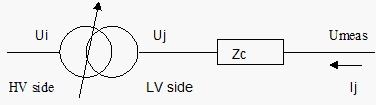
The voltage Umeas, on the basis of which the voltage control chooses a different tap, is:
Umeas = Uj + Ij * Zc
where:
Zc = Rc + jXc
The compounding in Vision takes into account the direction of the current due to the complex multiplication. Note: in practice it can occur that the absolute current value is assumed. In those cases, the model of the voltage regulation will respond differently when it is delivered back than in practice.
If Umeas> Umax or Umeas <Umin on the w2 side, a different tap mode is selected on the w1 side (until the minimum or maximum tap position is reached).
If the voltage regulation has to compensate the voltage loss over a certain connection, this can be done by indicating a compounding impedance Zc. The way in which Zc can be determined from a graph U = f (I) is indicated by the following figure.
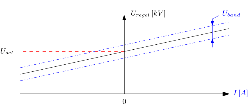
If Rc/Zc = cos(load), the following applies:
U / I = Zc
which can be used to determine Rc and Xc:
Rc = Zc * cos(φ)load
Xc = Zc * sin(φ)load
If the values found for Rc and Xc are given in the form, the transformer voltage will be dependent on the load current.
The dead band is located around the to be controlled voltage. The transformer will not change tap if the measured voltage is between Uregel - ½*Uband and Uregel + ½*Uband.
Reliability
Parameter |
Default |
Unit |
Description |
Failure frequency |
0 |
per year |
Mean number of occurrences that the transformer fails (short circuit) |
Repair duration |
0 |
minutes |
Mean duration of repair or replacement |
Maintenance frequency |
0 |
per year |
Mean number of occurrences that the transformer is in maintenance |
Maintenance duration |
0 |
minutes |
Mean duration of maintenance |
maint. cut-off duration |
0 |
minutes |
Mean duration of cancellation of maintenance in case of emergency |
Calculation
IEC 60909 and Fault analysis
In asymmetrical short-circuit calculations and fault analyses, the inverse impedance is equal to the normal impedance (Z1 = Z2).
The values of Re, Xe, Z0 and R0 are not relevant for the calculation of a symmetrical fault (FFF) or two-phase-fault without earthing (FF).
IEC 60909
A short-circuit calculation in accordance with IEC 60909 can be determined using a nominal tap (transfer ratio: Unom w1 /Unom w2) or using the transfer ratio which follows from the set tap.
The voltage control has no influence on IEC 60909 calculations. Transformers with voltage control are modelled in the same way as transformers without voltage control.
Fault analysis
Transformers with voltage control are modelled for the sequential failure analysis in the same way as transformers without voltage control. However, a load flow calculation is performed to determine the "pre-fault" situation (sequence 0). With this load flow calculation, the step position can be determined by the voltage regulation.