An overhead line can be characterized by its line impedances. The mutual impedances of the overhead lines are influenced by the conductor sizing and positioning. The impedance calculation has been based on Carson's method for overhead lines with earth return.
This tool can be started by choosing: Tools | Tools | Power lines
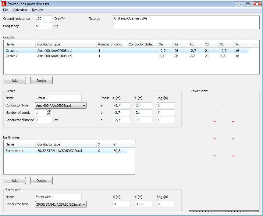
Base for the calculation procedure is the tower configuration, containing the conductor positions and their types. Also bundle conductors can be defined here. Once a configuration has been defined, it can be saved as: <Name>.txt.

Conductor type
The calculation uses conductor type data from the types file. These data are on the work sheet Lineconductor. The parameters are:
Name |
Unit |
Description |
Name |
Conductor type name |
|
Unom |
kV |
Rated voltage |
Inom |
A |
Rated current |
R |
Ohm/km |
Specific AC resistance |
Lint |
mH/km |
Conductor internal inductance |
d_ext |
mm |
Conductor outside diameter |
d_int |
mm |
Conductor internal diameter, if hollow |
Internal induction
The conductor self induction is the sum of the internal and the external induction. The external induction is a function of the conductor outside diameter. The internal induction can be calculated from the conductor material properties. A relationship exists between the internal induction, the relative permeability and the geometric mean radius.
The internal induction can be calculated from the relative permeability:
with:
For hollow conductors (0<q<r):
For solid conductors (q=0):
The relative permeability for a number of materials can be found in the table below.
Material |
μ r |
Copper (Cu) |
1 |
Iron (Fe) |
100-1000 |
Aluminium (Al) |
1 |
Bronze |
1 |
All Aluminium Alloy Conductors (AAAC) |
0.6 – 1.3 |
All Aluminium Standarc Conductors (AAC) |
1.0 – 1.3 |
Aluminium Conductor Alloy Reinforced (ACAR) |
0.8 – 1.1 |
Aluminium Conductor Steel Reinforced(ACSR) |
0.5 – 6.5 |
ACSR EHS (extra high strength) |
5.1 – 6.4 |
Allumoweld |
6.8 – 8.2 |
EHS Cooperweld |
22.3 – 35.4 |
When calculating the impedances of lines, the geometric mean radius (GMR) is used. In case the skin effect can be neglected, the GMR is equal to the geometric mean distance between all infinitesimal partial conductors in the conductor cross-section. For a solid conductor, consisting of magnetic material with a relative permeability of μr, this results in:
The internal induction can be calculated from the GMR:
Tower image
The conductors positions are presented in the tower image. Phase conductors and bundles are presented as red dots, while the earth conductor is presented as a green dot.
Calculate
This function calculates the positive and zero sequence impedances (Z1 and Z0) and the mutual impedances (Z00).
Circuits:
Name Z1 Z0
Ohm/km Ohm/km
-------------------- --------------- ---------------
Circ1 0,0842+0,4192j 0,2670+1,1620j
Circ2 0,0840+0,4195j 0,2584+1,1861j
Mutual coupling:
Circuit 1 Circuit 2 Z00
Ohm/km
-------------------- -------------------- ---------------
Circ1 Circ2 0,1787+0,7158j
Results
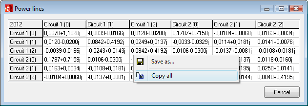
This function presents the results in a matrix. The right mouse button allows saving the results or copying to Word or Excel.

Pictures
This function enables the depiction of the tower construction. By right-mouse clicking in the field at Pictures, a pop-up menu appears, in which pictures can be added, deleted and shown.
