To perform a Security Analysis, the grid must meet a number of preconditions:
•the grid must have a correct load flow
•the grid must be protected
•all protection devices must be specified
•circuit breakers must be equipped with the probability of refusal, if applicable
•nodes, cables and connections should preferably feature the failure frequency.
Short circuits are simulated on all selected nodes, cables and connections. The failure frequency of those objects determines how often they occur on an annual basis. The function simulates short-circuits of different kinds and with different arc resistance.
The calculation can take a while. A timeline shows the progress.
The calculation is started with: Calculate | Protection | Analysis.
The calculation is performed for all selected nodes, cables and connections.
Options
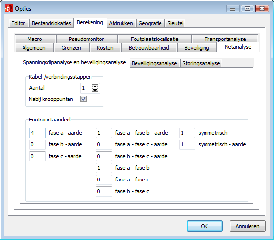
In the Options(Calculation | Network Analysis | General), it must be defined at how many points in the cables and connections a short circuit is to be simulated. By default, the Number of cable/connection calculation steps is zero. The maximum is 9. An option is included to also simulate a short circuit in the cable or connection near the nodes, at 1% and 99% of the length respectively.
The Error Rate should also be specified. This is a series of numbers that the user uses to indicate the weighting for the fault type against all possible short-circuits, summed in the failure frequencies. The example below shows that a single-phase earth fault is twice as common as a two-phase earth fault and a symmetrical fault. This means that for a user-specified failure rate of 0.02 /km/year for a cable, the failure rate for a single-phase earth fault equals 0.01 /km/year and for a two-phase earth fault and a symmetrical fault equals 0.005 /km/year.

An option, on the Security Analysis tab, concerns values for the resistance at the fault location. Optionally, 0 Ohm and two additional resistance values.
The second additional value is not used with cables. This second additional value is doubled in the calculation of single-phase faults.
An option, on the Protection Analysis tab, concerns the level of sequentially refusing protections (0, 1 or 2):
•refusal level 0: analysis of refusing switches is not performed
•Refuse level 1: analysis is performed for only one refusing switch
•refusal level 2: analysis is performed for two sequentially refusing switches
See also: