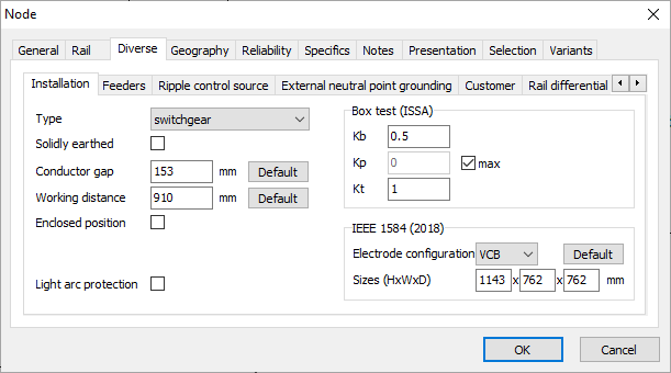
The parameters used for the arc flash calculation are to the large extent the same as for the short circuit current and protection calculations. There are several extra parameters necessary that can be set via node input data. On tab Specials -> Installation type and parameters of an installation are specified.

It is possible to choose between four different types of the installations: open air, switchgear, cable and motor control center MCC (the last option only for the nominal voltage up to and including 1 kV). Type of installation has influence on the distance factor in the IEEE 1584 calculation.
Solidly earthed checkbox specifies whether the network neutral is solidly earthed. This has influence on the coefficient K2 in the IEEE 1584 calculation.
Conductor gap is the distance between the conductors where the arc flash occurs. Default button fills in the typical conductor gaps from Table 2 of the IEEE 1584. However, it is preferable to use the real values of conductor gaps. For varying conductor gaps it can be advised to perform calculations for minimum, maximum and average gaps. In the IEEE 1584 calculation the conductor gap has influence on the arc current and the incident energy. In the ISSA calculation the conductor gap is in principle not used. The user can manually set the Kp factor based on the conductor gap value (using Table A1.1 of the ISSA).
Working distance is the distance between the conductors and the head/torso of a person (this is not the distance to hands of a person!). Typical working distances can be set using Default button (Table 3 of the IEEE 1584). However, it is preferable to use the real values of working distances. The working distance is used in both IEEE 1584 and ISSA.
Enclosed position checkbox specifies whether it is possible to escape from the arc in 2 seconds. In case the working position is enclosed, this is not possible and the calculation continues until the short circuit is completely isolated. Otherwise the calculation stops on 2 seconds (this is the rule of thumb from IEEE 1584). This option is applicable for both IEEE 1584 and ISSA.
‘Box test’ parameters are the parameters that are used only by ISSA. Their meaning is explained below.
Kb is the current attenuation factor. The arc current is equal to the product of the minimum short circuit current and the current attenuation factor. The typical value of Kb is 0.5.
Kp is the coefficient of the arc power. The arc power is equal to the product of the short circuit power and the Kp-factor. The value of Kp can be set manually (in case if the checkbox max is not checked) based on Table A1.1 of the ISSA. If the checkbox max is checked, then the coefficient is computed according to the following formula (dependent on the R/X ratio of the short circuit):
![]()
Kt is the transmission factor used for the calculation of the PPE protection level. This factor is dependent on the volume of the installation and varies between 1.0 and 2.4. The larger the volume is, the higher is the transmission factor. This means that the arc energy is evenly distributed in space (which reduces the negative effects of the arc on person). For example, the value of 2.4 are applied to open installations, while the value of 1.0 is typical for closed installations. Larger transmission factor results in higher protection levels of PPE.
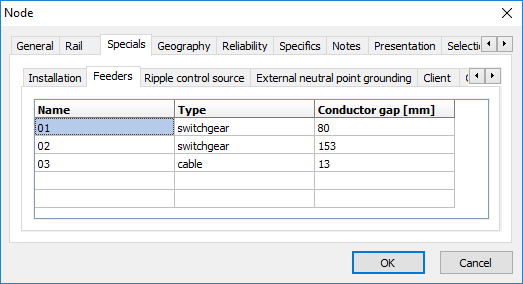
It is also possible to specify deviating parameters for ingoing and outgoing feeders (that are connected to the node). Namely, different types of installations and conductor gaps can be set. In case feeders are not specified, the parameters of the node are used also for connected feeders. Feeders can be coupled as given in Field.

The recent edition of the IEEE 1584 standard from 2018 introduces choice between different types of electrode configurations (open or closed, vertical or horizontal). Description of the types of electrode configurations and their photos are to be found in the standard. Further it is possible to specify dimensions for closed installations. Typical dimensions are given in Table 8 of the standard. It is however advised to use the actual dimensions. Specific parameters that are necessary for IEEE 1584 and ISSA calculation in Vision can be summarized in table:
Parameter |
IEEE 1584-2002 |
IEEE 1584-2028 |
ISSA |
Type installation |
Yes |
Yes |
No |
Solidly earthed |
Yes |
Yes |
No |
Conductor gap |
Yes |
Yes |
No |
Working distance |
Yes |
Yes |
Yes |
Enclosed position |
Yes |
Yes |
Yes |
Kb |
No |
No |
Yes |
Kp |
No |
No |
Yes |
Kt |
No |
No |
Yes |
Electrode configuration |
No |
Yes |
No |
Dimensions |
No |
Yes |
No |