The mutual coupling is a value, representing the electro-magnetic coupling between parallel lines. Through this mutual coupling the line currents in both lines are influenced by one another, especially in the case of unbalance. The effect is particularly visible in case of a phase to ground fault in one of the parallel lines. For this reason the mutual coupling has been modelled as an impedance in the zero sequence system.
The mutual coupling can only be applied to lines.
The mutual coupling has an effect on the zero sequence impedance and is modelled for the asymmetrical short-circuit calculations: fault analysis and IEC (60) 909.
Multiple connections, that are mutually coupled together, form a mutual group. Such a mutual group has been limited to a maximum of 10 mutual couplings. The number of mutual groups has not been limited.
A mutual coupling has been modelled for the whole length of the mutually coupled connections between the "from" and the "to" nodes. In case of a T-connection, auxiliary nodes should be added (see below).

New
A new mutual coupling can be defined by firstly selecting the two parallel connections and secondly choosing from the main menu: Insert | Branches | Mutual coupling.
Always mind the proper directions of both mutually coupled connections. If both connections do not have the same direction, the effect matches that of a negative mutual impedance.
Select
Normally, mutual couplings are not visible in the network diagram. Using a special select function the branches with a mutual coupling will be selected: Start | Select | Special | Mutual connection.
Edit
An existing mutual coupling can be edited by first selecting the two parallel connections and subsequently choosing from the main menu: Start | Edit | Mutual coupling or using the keys: Ctrl-Alt-M.
Delete
An existing mutual coupling can be deleted by first selecting the two parallel connections and subsequently choosing from the main menu: Start | Edit | Delete | Mutual coupling.
Parameters
Parameter |
Default |
Unit |
Description |
R00 |
0 |
Ohm |
Mutual coupling zero sequence resistance |
X00 |
0 |
Ohm |
Mutual coupling zero sequence reactance |
Modelling
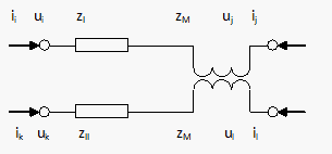
The schematic of a basic model of two parallel connections, which are interconnected via an impedance ZM, is shown below:

In the case of two connections with a mutually coupling, an impedance occurs in the branch impedance matrix. The following equations in the zero sequence system relate to two connections between nodes i and j and k and l with impedances ZI and ZII and mutual coupling ZM:
uij = ZI ⋅ iij + ZM ⋅ ikl
ukl = ZII ⋅ ikl + ZM ⋅ iij
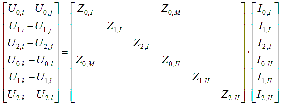
In practice, mutual couplings are modelled only in the zero sequence circuit, so that the equations for two circuits according to the symmetrical component method changes to:
