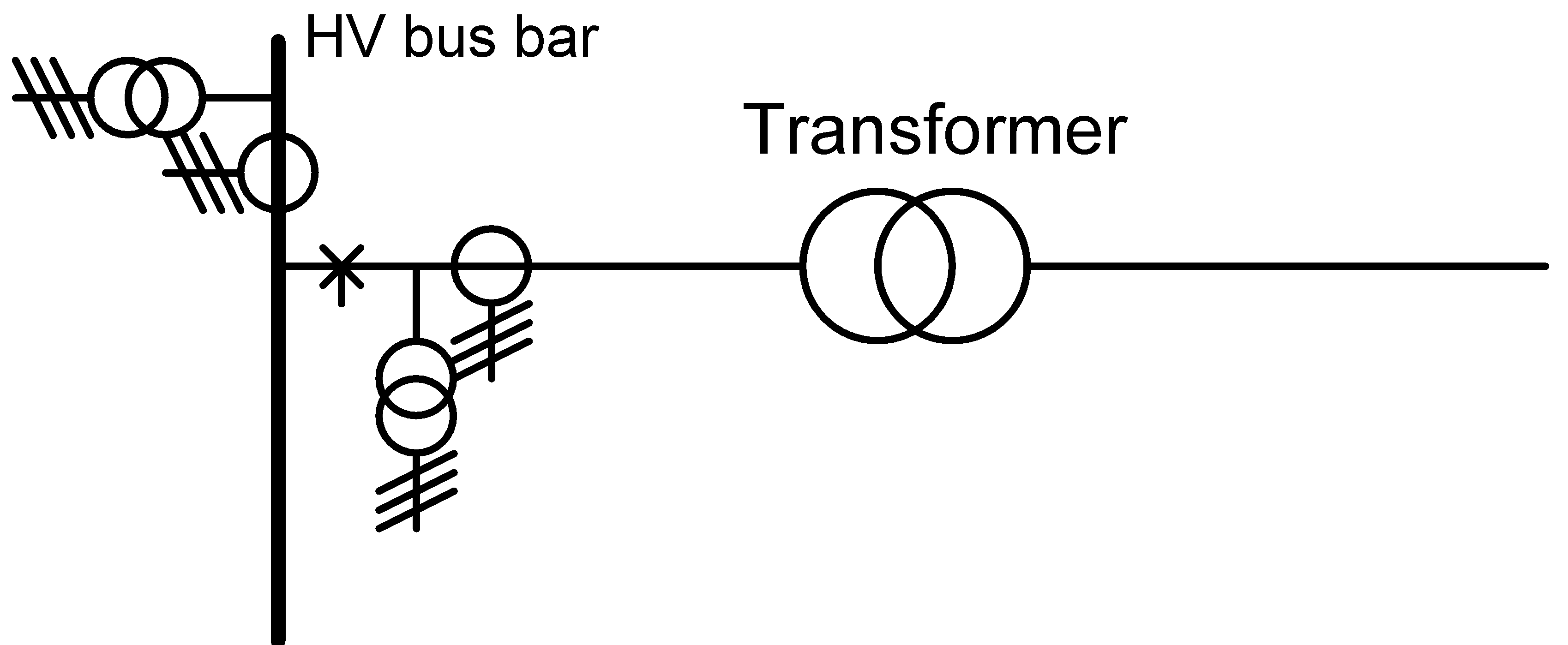
The presence of one or two or three current measurement transformer(s) and a single voltage measurement transformer can be specified. A measure field can be placed at a node or in a field on both sides of a branch or on an element.
To add a measure field, select a single node or select a branch or an element and the corresponding node and choose: Insert | Switches and protections | Measure field.
The measure transformer has the following attributes:
•function
•class
•transformer ratio
•rated power (VA)
•Inom: rated current of the current measurement transformer (A)
•Ik,dynamic: dynamic short-circuit current (kA)
•Ik,thermal and tthermal: thermal short-circuit current (kA) and duration (s)
The rated current of the current measurement transformer is used in the load flow calculation and the protection analysis.
The Ik,dynamic is tested when applying the IEC 60909 short-circuit calculation.
The Ik,thermal and tthermal are used to calculate the tmax in the IEC 60909 short-circuit calculation.
Measurements
A list of dates with corresponding measurement values can be entered. If the value ends with 'A', 'kW', 'MW', 'kVA' or 'MVA', a date-current graph or a date-power graph is displayed. With the button ... you can switch between these two options. Only the last 12 measurements are displayed.
The graph can be shown as a bar graph or as a line graph by means of two buttons. A point graph is used instead of a line graph if a time interval is greater than twice the average time interval.
Selected measurements can be removed with Delete. Select multiple measurements with Shft+cursor-keys.
All measurements can be copied to the clipboard as text with Copy.
Measurement files
A list of Excel-measurement files can be imported. For the time being, this is only for illustrative purposes.
In the Column(s) field, one or more columns can be specified that contain the measured values. This can be done in two ways:
•By entering the column letter (s), e.g. A, B, C, etc.
•By filling in the text that is in the cell of the first row of the relevant column, e.g. Imeasured.
If this column only applies to a particular worksheet, the name of that worksheet can be placed in front of the column, with an exclamation mark between them (in accordance with Excel), for example: MySheet!G or ThisSheet!Current.
Multiple columns can be entered consecutively, separated by a semicolon.
The worksheet is deemed to contain a date-time column or a date column and a time column. These are automatically detected by searching for "date" and "time" in the first two rows. If this is not successful, the first column is considered to be the date-time column.
The Graph button displays a line and/or a scatter plot of all the measurement files with indicated columns.
The Graph + make profile type button also generates non-standard profile types that can be included in the object type file after normalisation.
If a load flow with profiles has been executed, the result is also shown as a series in the graph, provided the measurement files show a quantity that is also available as a load flow result.
A copied measurement unit can be pasted into multiple feeders at the same time. Select the feeders to which the measurement unit should be copied and choose: Start | Clipboard | Paste special | Paste switch in all selected
The symbol of the measurement field can be flipped to the other side of the branch or the node by dragging it with the mouse. The symbol can be moved along a node.
