IEC 61363 standard describes models of the following active elements:
•synchronous machines (see p.29, Section 5.1.1 of the standard)
•asynchronous motors (see p.37, Section 5.1.2 of the standard)
•converter-connected motors (see p.45, Section 5.1.4 of the standard)
Further, the models of the following branch components are given:
•cables (see p.47, Section 5.2.2 of the standard)
•transformers (see p.47, Section 5.2.3 of the standard)
•reactors (see p.49, Section 5.2.4 of the standard)
The short description of these models is provided below.
The following elements of Vision are not supported by the IEC 61363 calculation:
•external network (source): networks of ships/offshore units operate typically in island mode
•wind turbine
•PV
•accumulator
•grounding transformer (zigzag coil)
•shunt capacitor
•shunt reactor
•transformerload (transformer and load as one element)
Synchronous generator and motor
The synchronous machine is represented by an internal e.m.f. (electromotive force) behind resistor and reactor. The short-circuit current is divided in three periods: subtransient, transient and steady-state. The parameters of machine have to be specified for each period. IEC 61363 uses the approximation of synchronous machine with only d-axis reactances (q-axis reactances are neglected).
The envelope of the total short-circuit current in time (instantaneous values) is:
![]()
AC-component of the short-circuit current (RMS values) is:
![]()
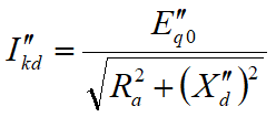
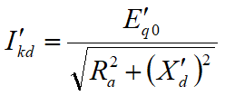
where subtransient and transient components of the short-circuit current are calculated as follows:


Internal e.m.f.’s are dependent on the voltage, current and power factor just before the short-circuit (pre-fault situation):


Steady-state short-circuit current is calculated in an analogical manner. If Ikd parameter (tab Dynamic of the synchronous machine) is specified, the correction to the synchronous reactance Xd is applied such that the steady-state short-circuit current is equal to the specified value. If the option ‘Use Ikd parameter of synchronous machines’ is checked (see Vision Options, tab Calculation and then tab IEC 61363), then the synchronous reactance also corrected such that Ikd is at least 3 times larger than the nominal current of the machine.
DC-component of the short-circuit current (instantaneous values) is:
![]()
where DC-time constant Tdc can be specified explicitly (see tab Dynamic of the synchronous machine) or determined implicitly via the following equation (if ‘Tdc unknown’ option at the tab Dynamic of the synchronous machine is checked):
![]()
The peak current of the short-circuit is defined by the standard as the total short-circuit current ik at time t = T/2 (for 50 Hz: 10 ms, for 60 Hz: 16.7 ms).
Asynchronous motor
The asynchronous motor is represented by an internal e.m.f. behind resistor and inductor. Asynchronous motors feed only subtransient short-circuit currents to the network. There is also aperiodical (DC) component present in the short-circuit current of the machine.
The envelope of the total short-circuit current in time (instantaneous values) is:
![]()
AC-component of the short-circuit current (RMS values) is:
![]()
where the subtransient short-circuit current is:
![]()
Internal subtransient e.m.f. is dependent on the pre-fault situation (voltage, current and power factor of the motor):

Equivalent resistance and reactance of the motor are:
![]()
![]()
DC-component of the short-circuit current (instantaneous values) is:
![]()
Time constants of the motor are calculated from stator and rotor resistances and reactances:
![]()
![]()
The peak current of the short-circuit is defined by the standard as the total short-circuit current iM at time t = T/2 (for 50 Hz: 10 ms, for 60 Hz: 16.7 ms).
Parameters of the asynchronous motor (RS, RR, XS, XR) can be filled-in on tab Dynamic of the respective motor. The option ‘Own parameters’ has to first checked in order to do this. In case this option is not checked, the resistances and reactances are estimated from the locked-rotor data, critical torque and the nameplate data. In case ‘double cage’ model is chosen, the equivalent rotor impedance is calculated using parallel connection of the first and second rotor circuit.
Converter-connected motors
Converter-connected motors do not contribute to the short-circuit current.
Cable
All cables are represented by a series connection of resistor and inductor. According to the standard the shunt capacitances of cable are neglected. The resistance of cable is adjusted based on the conductor temperature. This occurs in case the option ‘Apply conductor temperature’ in Vision Options on tab Calculation | General is checked. The adjustment due to temperature takes place in the same manner as for IEC 60909. The correction factor is equal to:
![]()
where Tref,° is the reference temperature (specified in the type-file) and Tact,° is the actual temperature (specified in Options).
Transformer
The transformer is modelled by a series connection of resistor and inductor. Parameters are calculated from data of the short-circuit test. Taps of the transformers are set to the nominal positions.
Reactor
The reactor is represented by a series connection of resistor and inductor.
Link
The impedance of link is neglected in the IEC 61363 calculation. Nodes (busses) connected to each other by the links are considered internally as one node (bus).
Load
The load does not feed short-circuit current to the network. Therefore the loads are not considered during short-circuit calculation. Loads have influence only in case the loadflow calculation is used for initialization of IEC 61363 calculation.